
As I am writing (March 23, 2020) more and more of us are staying home and maybe spending time in our Ham stations. We are fortunate to have amateur radio as both a hobby and a way to provide service to the public. While I hope this challenge passes soon, we can take this opportunity to refresh our appreciation of amateur radio, staying in touch with friends the world over. Best wishes to all of our readers!
Even in the milder climates of the northern hemisphere, the winter months take a toll on amateur stations. Windy, wet weather finds a way to wear out connections and drive water into some unexpected places. Ice and snow load down antennas and supports, force their way into mechanical joints, and loosen bolts and nuts by repeated cycles of heating and cooling. By the time spring rolls around, your station’s outdoor components have been worked over pretty thoroughly by Old Man Winter!
But now it’s spring and time to start planning those new “skyhooks” (antennas), isn’t it? Not so fast. First, you need to check up on the ones you already have. Even if everything seems to be just fine, the first few mild-mannered days are the perfect time for your Spring Station Inspection, the subject of this article.
Focus on Outside
While a station inspection can be done anytime, in early spring the most important components are outside where they’ve been subjected to the winter weather. We’ll cover the most common outdoor items, things that often happen to them, and what you can do to find problems. The inspection can be done in any order, but we’ll start at where your feed lines come indoors. While you’re inspecting, you’ll probably find things to fix. Unless the problem is an easy one, like a loose nut, keep a list of repair jobs and keep going on the inspection so you get it all done. It’s easy to get distracted.
SWR Check
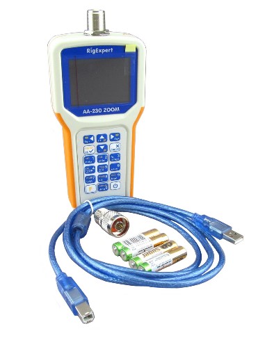
Part of checking the outdoor items starts indoors with an SWR check. Hopefully you recorded the SWR versus frequency for each antenna as it was installed. That’s the time to take an SWR snapshot—when the antenna is tuned up, its feed line new, and connectors clean and tight. The right place for recording those measurements is your shack notebook. If you don’t have one, this might be a good time to start, with your inspection result entries. The RigExpert AA230 ZOOM Analyzer (below) gives you a graph of SWR vs. frequency, and you can store the data on your PC.
Measure and record the minimum SWR for each of your antennas and the frequency at which it occurs. Also measure the frequencies at which SWR reaches 2:1—this is your SWR bandwidth—or record what the SWR is at the band edges. Make measurements where the antenna system feed line connects to your transceiver. Compare these measurements to those taken when the antennas were placed into service.
What you’re looking for is either big shifts in the minimum SWR frequency or SWR values. If your antenna SWR curves look about the same as they did in the last inspection, make a note of it. If you find significant discrepancies, flag that antenna for a close inspection and move on to the next one.
While you’re at it, do a visual inspection of the feed line and connectors inside the station. Disconnect the feed lines one at a time to make sure the connectors aren’t corroded or loose. Bulkhead connectors that extend through an exterior wall often collect condensation on their inside portion during cold weather. Clean any corrosion off all threads, pins, and sockets—a cotton swab with a little contact cleaner will get into an SO-239 center socket rather nicely. If you do find a severely corroded or damaged connector, make a note to replace it and put a piece of colored tape on the bad cable or connector so you can find it later.
Feed Lines and Connectors
While you’re focused on feed lines, proceed to the entry panel for your feed lines, if you have one, or any outside connectors. If your connectors are weatherproofed with tape or sealant, do a close visual inspection for cuts, rips, tape coming unwrapped, etc.—any place that water can get in. Small holes can be repaired, but large defects require the weatherproofing to be removed and replaced, possibly along with the connectors.
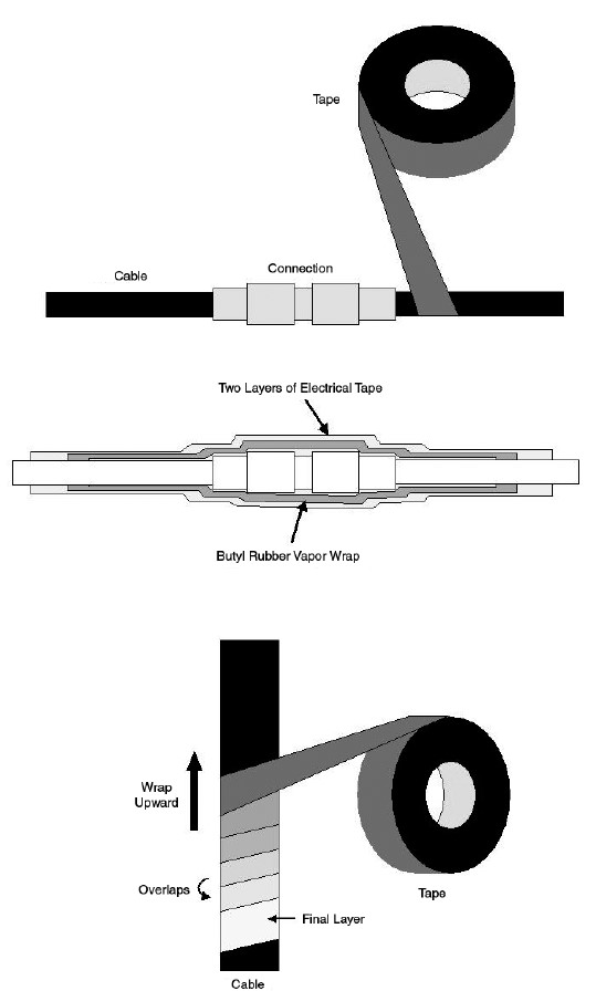
The graphic below shows a recommended way of weatherproofing RF connectors by wrapping them with self-fusing rubber splicing tape and electrical tape. Severe conditions may require extra coatings of sealant, but in most amateur installations, a layer of vapor wrap or self-vulcanizing tape, covered by a double wrap of high-quality tape such as Scotch 33+ or Scotch 88 will work. This is no place to save money on tape! Using tape adds UV protection and makes it much easier to get the weatherproofing off at a later date, if necessary.
Inspect the entire length of your feed lines for jacket damage wherever they are exposed, including the important rotator loop at the top of a tower. Repeated movement can cause a feed line to chafe against something and wear a hole in the jacket. Allowing water inside contaminates the shield and causes loss to increase. Flexing in the wind can cause cracks in a jacket or work a cable loose in a connector. Hungry animals can nibble on a plastic jacket as well. When you take SWR measurements, an SWR curve that looks “too good”—lower SWR than expected or much wider SWR bandwidth—may mean water has gotten into the feed line.
Handy Tip #1: Whenever you head out to the antennas for any reason, take along a roll of good tape, a sharp knife, and a pair of lineman’s or gas pliers. If you happen to notice something working loose or needing a wrap of tape, you can take care of it on the spot.
Open-wire lines have their own challenges. One common problem, particularly for the lines constructed with solid copper or copper-plated steel conductors, is metal fatigue. Repeated bending or flexing can break the wire, including inside the plastic insulation. This is why it’s a good idea to provide stress relief wherever the line is attached to an antenna or device like a balun or transformer.
Accessories
Coax switches need special attention. With all those feed lines coming to one spot, it’s easy to overlook a loose connector or water damage. If you suspect water (or insect) penetration, you’ll need to take the cover off to have a look. If you can, route the cables to keep water away from the switch with a drip loop.
Matching assemblies like gamma matches or shunt feed structures are exposed to water, so you need to take a close look at all of the clamps, screws and nuts, and any sliding sections or straps. When assembling them, you should apply a thin coating of anti-oxidation compound, such as Jet Lube SS-30 Pure Copper Anti-Seize, to both keep the water out of the joint and prevent oxidation. Check to be sure every mechanical connection is tight and corrosion-free.
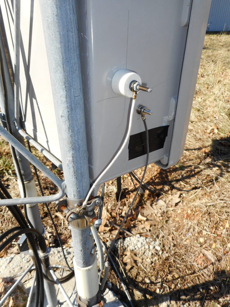
Tuning or matching networks are usually in some kind of enclosure. As always, check the coaxial connections. Pay special attention to any insulators or wire feed-throughs as in the photo below. The screw terminals will loosen with repeated thermal cycling, even if a locknut is used—a good argument for using a thread locking compound.
Tighten all of the connections and be sure the anti-oxidation compound on the terminals hasn’t washed away. Clean any corrosion with a brass bristle brush or some other non-damaging tool.
Handy Tip #2: A yogurt cup filled with old-fashioned napthalene mothballs will help deter “critters” from nesting in outdoor enclosures. Refill it in the spring and fall.
Make sure any enclosure drain
holes are clear. Bushings or feed-through insulators can wear and leak, so
check gaskets or washers where water might get in. Clamps to tower legs and
ground rods must be checked for corrosion and tightened, if necessary.
Antennas and Rotators
The next things to inspect are the antennas themselves. Since there are so many variations, I’ll just make a list of things to check. You can figure out what applies to your antennas:
- Is the mounting hardware secure?
- Is the feed line securely attached and weatherproofed?
- Are any elements out of alignment?
- If possible, check telescoping element clamps for tightness.
If you saw a shift in SWR from inside your station, you’ll have to do a little troubleshooting. Ask yourself what the symptoms are telling you. If the minimum SWR point shifted higher in frequency, look for some part of the antenna that may have gotten shorter by slipping in a clamp or moved farther from other parts. An SWR point that moves lower in frequency can be the result of antenna parts moving closer together or getting longer. Something laying on the antenna can have the same effect—perhaps a tree branch or support line blown into the antenna. Intermittent SWR generally means something is loose, often at the feed point or in an impedance matching assembly. The ARRL Antenna Book has a big section on antenna system troubleshooting that may be helpful.
Rotators need to be checked as well:
- Check motor, brake, and indicator resistances as specified in the manual
- Inspect outdoor control cable connections
- Check rotator mast clamp tightness
- Check antenna mast orientation (set rotator to a known direction in the station first)
- Check the mounting bolts that hold the rotator to the tower
For wire antennas, you’ll need to inspect the feed point, the end insulators, and the supporting ropes or cables. Feed points can be a particular problem if the feed line is hanging from the antenna without any other support. Make sure the feed line is securely attached to the antenna itself. Soldered connections can work loose or oxidize. Inspect all insulators for cracks or carbon tracks that indicate an arc. Finally, take a good look at ropes for fraying or damage from rubbing on a branch. Pulleys should operate smoothly as well.
Towers and Masts
You’ll need to pay extra-close attention to your antenna supports all year long but especially in spring after winter does its work. Bolts work loose, turnbuckles can twist, clamps can slip. There are many potential failure points, so take your time.
Two references you should absolutely have on hand are Antenna Towers for Radio Amateurs by Don Daso, K4ZA, and Up the Tower by Steve Morris, K7LXC. These two books cover just about every aspect of tower work involved in a typical station. They complement each other nicely, starting with construction all the way through rigging to get antennas installed.
If you have a multi-section mast, either fiberglass or metal, start by checking that it is plumb vertically (use a carpenter’s level) and not bent (look up along its length from the base). Lower it for inspection if you can. Check each section clamp and all of the guy attachments. Inspect all of the guy ropes or wires along their lengths and at the ground-level clamp or attachment point. Be sure the guy points themselves are secure and not working loose in the ground. If the mast is attached to a building support, make sure it is securely fastened to the underlying structure.
A lattice-style fixed or crank-up tower requires careful attention due to the tension and weight involved. As with a mast, start by verifying that the tower is vertical and straight. Before you begin climbing, do a careful inspection of the base. Look for corrosion where the base emerges from the footing and the dangerous situation of a split tower leg from water collecting in the tower leg and freezing. If any of these are present, do not climb the tower!
Handy Tip #3: When working on or inspecting galvanized masts and towers, take along a can of “cold galvanizing spray” and a small steel brush. As you climb or work, take a minute or two to brush off any light rust or clean a damaged spot in the galvanizing. Then coat it with the spray galvanizing paint.
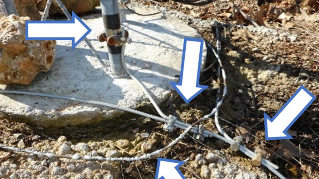
Next, inspect all of the ground connections, verifying that all clamps are secure and the connections are clean. This includes any radials if the tower is used as a vertical. All components of the ground system must be bonded together with heavy wire or strap as in the photo.
Check each guy point carefully. Guy wires should be secure in the saddles. If you use Crosby clips, check that they are tight and that the guy wire has not slipped. If you use friction grips (a.k.a. “Big Grips”), be sure they have not unwound or slipped. Inspect a crank-up’s lift cable for fraying or broken strands along with the lift winch hardware and mounting brackets.
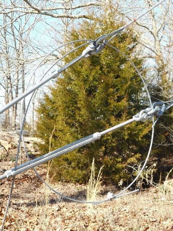
Inspect the safety wire that goes through the guy wire loop and through the tension adjust turnbuckle as shown in the photo above. The safety wire keeps the turnbuckle from loosening because of vibration caused by wind. Check the shackles at each end of the turnbuckle and verify the bolt and nut are secure. Check each bolt and nut on the guy point. This is particularly important during the tower’s first year because of thermal cycling, stretching, and vibration.
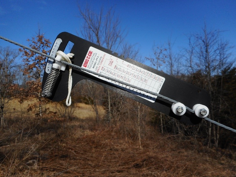
Next, measure the tension of each guy wire. The most common tool for this purpose is the “Loos Gauge” shown in the photo above. The PT-2 model is calibrated for 3/16-1/4″ EHS steel cable, the sizes most amateur installations use. Slip the cable between the pegs and into the spring-loaded meter pointer. The pointer indicates a value from 0–50 which cross-references to a specific tension value in the table on the gauge. Record the value for each guy wire and compare it to previous inspections. Look for significant lessening of tension due to slipping or stretching.
Assuming the base and all of the guys are in good shape, it’s time to climb the tower. Take a pair of wrenches that fit all of the nuts and bolt heads holding each section together. Check each one! They should be snug but not so tight that a tubular tower leg is deformed. (The legs of pressed sheet metal towers such as the Rohn DBX/HDBX lines can be bolted together as tightly as you want.) Check each guy attachment just as you did for the ground end of the guy wire. A final few words about tower safety: Never climb any tower unless you are properly trained and physically fit for the job, all conditions are safe for climbing, and you are wearing approved fall prevention and fall arrest gear.
Planning
Take a break and think about what your inspection has found and the ideas you’ve had along the way. Break out your notebook and make notes while everything is fresh in your mind.
If you found something that needs work to repair, think about what will be required to remove and rework it. If you are thinking about adding some more antennas—and who isn’t?—look around and consider what it will take to add them. Where will the feed lines go? How will you lift the new antenna around existing antennas? That sort of thing is much easier to visualize when you’re on the tower or looking at the mast.
Use your phone’s camera or a pocket-sized point-and-shoot camera to take photos of everything in your antenna system. Start at the feed line entry panel and continue all the way to the top of the tower. That way you won’t have to rely on memory when planning a new project or trying to remember “what went where.” When you’re finished, put all of the photos into a folder labeled something like “Inspection Photos – Spring 2020.”
Finally, take a minute to enjoy the view and snap a photo or two of the scenery as well. Listen to what you can hear “up there” that you can’t on the ground. It’s not a race and not many people get to climb towers or trees and work on antennas, you know — enjoy the view!
Pingback: The ARRL Contest Update for April 15, 2020 – Big Island ARRL News