
Antenna analyzers are generally used during the building and tuning of antennas. It’s a tool that helps you physically adjust the length of the antenna and check the entire antenna system, including the feedline. Antenna analyzers have become a very popular accessory—and sooner or later, many hams will add one to their collection of test gear.
The advantage of an antenna analyzer is you don’t need a bulky transceiver for a signal source. As a lightweight, self-contained unit, the analyzer has a built-in low-power signal generator which allows testing beyond the edges of the amateur radio bands and doesn’t interfere with other stations on the air. With measurement and display systems combined into a small package, plus built-in battery power, they’re perfect for use in the field.
OCD about SWR
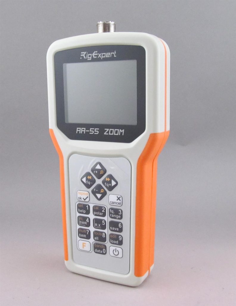
The most common use of an antenna analyzer is to measure antenna SWR (Standing Wave Ratio), something hams often obsess over. Analyzers can display SWR on a specific frequency, across an entire band, or even several bands at once—especially useful for multiband antennas. They’re built to cover a specific range of frequencies (for example, the RigExpert AA-55ZOOM-BT covers 0.06 to 55 MHz).
Once your antenna is constructed, it’s time to run a check. It should be off the ground, preferably within your reach, so you can adjust the lengths easily. Be sure that any baluns, ununs, or chokes are installed before you begin your testing. Also, don’t stand too close to the antenna—being in the near-field of the antenna will affect your results.
Connect the analyzer to the antenna with a piece of coax to begin your SWR sweep. Based on data from the analyzer, adjust the antenna dimensions to make it as close to resonance as possible. Some analyzers have graphic displays to make the data easier to understand than a simple meter or digital readout. Models like these can quickly produce multiple graphs for multiband antennas and connect to an external computer. Be sure to take notes on your results.
When building dipoles, wrap the wire over itself to shorten rather than trimming the wire. It’s much easier to adjust if needed. Note that the resonant frequency rises as the antenna approaches 0.5 wavelength above ground and then decreases as it reaches one wavelength high.
You can even pretune a beam antenna on the ground before putting it up without the ground affecting SWR measurements. Test the antenna pointing straight up, with the reflector several feet above the ground. This might involve a wooden ladder or post and some ropes. In your quest for a perfect match, trying to reduce your SWR from 1.5:1 to 1:1 is generally not worth the time. From a practical standpoint, an SWR of 1.5:1 is virtually indistinguishable from a perfect match of 1:1. SWR numbers in the range from 1:1 to 1.5:1 mean the antenna is radiating most of the power fed to it.
Vertical Antennas
A 1/4-wave vertical is just half of an antenna–the equivalent of one leg of a dipole. To get an accurate SWR reading, you need to have the antenna in place, complete with radials or counterpoise (the other half).
Vertical antennas present an interesting paradox. Adding more radials will noticeably improve antenna performance but drop the feedpoint impedance to approximately 36 Ohms, causing the SWR readings to increase. A basic 1/4-wave vertical antenna with a good set of radials, fed by 50-Ohm coax, will have an SWR of approximately 1.4 to 1. In this case, antenna performance is preferable to a small increase in SWR.
Multiband antennas are a bit more complex to adjust. Start by adjusting the length of the shortest section for the highest frequency band. Then move to the section of the antenna for the next lower band and so on until you have all sections matched. For example, if you’re tuning a Hustler 4BTV, you’d start with the 10m section, followed by 15m, 20m, and 40m. You may need to go back and forth a few times to get it right. Also note that multiband antennas may use coils and capacitors along their length, so these adjustments can be sensitive.
Mobile antennas should always be tuned in place on the vehicle. You should park the vehicle as far from any buildings, light posts or metallic objects as possible. Always take your measurements with all doors or hatches closed. Most VHF/UHF mobile antennas are already pretuned from the factory and only require basic assembly and mounting. With magnetic mount antennas, get as much metal under the antenna as possible—the roof is an excellent choice.
The rubber duck antenna by itself does not have a built-in counterpoise/ground plane, making it difficult to determine an accurate SWR. When you connect the rubber duck directly to the antenna analyzer, don’t be surprised when you get high readings. When the antenna is connected to the handheld radio, the radio itself acts as a counterpoise. They use the metal parts of the chassis as the ground plane, so it has a relatively good match when installed on the radio. However, it’s not as efficient as having a true 1/4-wave ground plane under the antenna.
If you’re determined to measure SWR on a rubber duck, try adding a single 1/4-wave wire attached to the ground side of the connector on the rubber duck antenna. Stretch it out straight and angled down a bit and measure again. SWR readings should improve. Remember that the “duck” is in a sealed assembly and isn’t meant to be tuned.
Tips and Tricks
Antenna analyzers can do many other useful things that could have you utilizing such a tool more often. Learn some of the additional functions and it might become one of your favorite pieces of ham gear. The information listed here is based on the RigExpert AA-55 antenna analyzer. Specific directions may vary among different brands, but the procedures are similar.
Display All Parameters: This screen displays values for series as well as parallel models of the impedance of a load.
SWR on Multiple Bands: This mode can be useful for tuning multiband antennas. You can see SWR readings for up to five different frequencies. Pressing the OK key will calculate the SWR values. New frequencies can be added or changed as needed. You can also choose to view mini SWR graphs for each band.
Cable Length Measurement/Velocity Factor: Maybe you have a cable running through the wall and need to know its length, but only the ends are accessible. In the Tools section of the menu (F, 8), enter the coax velocity factor to find the cable length. When you enter the cable length, it will calculate the velocity factor.
Cable Fault Location: To locate the position of a fault in a cable, just use the same method as when measuring its length. Watch the behavior of the reactive component (X) near the zero frequency. If the value of X is moving from –∞ to 0, the cable is open-circuited; if the value of X is moving from 0 to +∞, the cable is shorted.
Intermittent Connection: For a rotatable antenna, the rotor loop feedline is often the first component to cause trouble. Any significant variation in the SWR sweep display while the antenna is being rotated could indicate an intermittent connection or water in the coax.
Feedline Loss: All feedlines have some loss; bad feedlines exhibit more loss than others. We can measure feedline loss between the shack and an antenna without climbing a tower. In the Tools section of the menu, you’ll find a loss vs. frequency chart. There are two steps: connecting an open circuit cable followed by a scan, and by shorting one end of the cable followed by a scan.
Dip Meter/Tuning Traps: An antenna analyzer can work as a dip meter—it has an oscillator and a detector. Select the SWR chart function and attach a small coil to the analyzer using a short patch cable. Place the coil near a tuned circuit, such as an inductor or antenna trap. The maximum amount of energy is coupled to the tuned circuit at its resonant frequency, producing a dip on the chart. Tuning the circuit moves the dip, allowing you to tune the circuit to the desired frequency.