
The receiving antennas covered in this article are small enough to fit on residential lots or to use with a portable station. They are not transmitting antennas! Most are relatively low-profile and don’t require tall supports. We’ll omit the long Beverage antennas, including the “BOG” (Beverage On Ground) and large arrays of vertical whips. The goal is to help you hear another “layer” of stations that are weaker than the noise level at your station.
Signal-to-Noise Ratio
The advantage of using these small receiving antennas is not that they pick up more signal. There’s usually plenty of signal available—it’s just covered up by noise. What we’re really after is a better (higher) signal-to-noise ratio (SNR). There are two ways to improve SNR: pick up more signal or pick up less noise. While DSP is getting better and better at noise reduction (NR), the best solution is to pick up less noise in the first place.
Compared to a full-size transmitting antenna, these receive antennas will pick up comparatively little signal. In fact, you’ll probably need at least 10 dB of preamplification and often as much as 30 dB. (Take steps to protect the preamp if the transmitting antennas are nearby or high power will be used.) Nevertheless, the antenna rejects more noise than signal, so the net result is a better SNR.
Let’s start with a short discussion of noise.
Noise Sources
Where does the noise come from? On the HF/MF low bands, noise comes from three types of sources: atmospheric, human-made electrical static, and human-made interfering signals. Atmospheric noise can propagate worldwide from sources—mostly thunderstorms—that are very powerful. Human-made electrical noise is static typically caused by motors, arcs from power lines, and current-carrying contacts opening and closing. Finally, human-made interfering signals include radiation from computer and network equipment, switchmode power supplies, power-control circuits in appliances and other equipment, and unintentional radiators that use RF signals internally but leak some of the signal. Once your antenna picks up this noise, if it’s of the same frequency as the desired signal, it becomes an in-band signal and can’t be removed with a filter.
The best noise-fighting technique is to eliminate as many local noise sources as possible. Start in your own home by turning off or unplugging appliances and computers while checking received noise levels.
If you find a noisy “wall-wart,” router, PC, or appliance, take the necessary steps to eliminate that noise. Do the same around your neighborhood. You can sometimes determine a source’s direction with a rotatable antenna, but often you just have to drive or walk around while listening to the noise. If you find a noisy power pole, write down all of the ID numbers on tags attached to the pole (or take pictures of them) before calling the utility.
Don’t Let Noise In
Another way for noise to get into your radio is by being picked up as common-mode current on the outside surface of cable shields (or unshielded conductors) which travels along the cable. At any break in the shield, the current will enter the cable and become a differential-mode signal. This can happen at any frequency, regardless of what the cable is connected to or the signals it’s intended to carry. Once inside the cable, the noise acts just like any other in-band signal.
The way to prevent this from happening is to block the current by putting a high impedance in its path into the cable. That is what feed line chokes or current chokes do—they either block the current or dissipate it as heat. A feed line choke can be a simple coil of cable or ferrite cores on the cable. Place a choke at the antenna feed point where the feed line is opened up. Other good places for chokes are the station entry panel, at an antenna tuner, or at the radio itself.
Antenna Pattern Null
Wasn’t this article supposed to be about receiving antennas? Well, yes, but once you’ve eliminated as much noise as you can, the antenna’s noise-rejecting properties can be used more effectively!
The most important aspect shared by these antennas is not the amount of forward gain or a narrow forward beam, but the antenna’s overall directivity. Some have a very sharp, deep null that can be aimed to reject noise from a particular direction. Others may intentionally not receive signals over a range of directions. The antenna’s receive directivity factor (RDF) is the measure of its directivity. (W4RNL wrote an excellent article on antenna directivity you can read for more information.) If the antenna is rotatable, the direction for the best SNR may not be with the antenna’s peak gain in the signal’s direction but with the null or low-signal range positioned to reject the most noise.
For best performance, the antenna should be carefully constructed so that the noise rejection null or directivity is maximized. This may mean taking extra care to make the antenna as symmetric as possible. A load’s resistance may need to be adjusted to the right value. Dimensions should be exactly as in the design description. The feed line should be decoupled at the antenna and elsewhere to prevent noise pickup and interaction between the feed line and antenna. The antenna itself should be located to minimize interaction with transmit antennas.
The goal is to preserve the antenna’s noise-rejecting characteristics.
Coaxial Loop
A popular antenna from the dawn of radio is the small receiving loop, sometimes with multiple turns to pick up more signal. It is made from a circular loop of semi-rigid coax (hardline) with a short gap in the shield where the top support attaches. (Transmitting loops are similar but do not use coaxial cable and construction must be sturdier.)
This design is sometimes referred to as a “shielded loop,” but the signal is picked up by the outer surface of the coax. It then couples to the inner conductor which is connected to the feed line through a tuning capacitor that resonates the loop. A preamplifier is required to increase the signal to useable levels, making it an active antenna. (See W8JI’s website for detailed information about how this loop actually works.)
The modern equivalent, used at higher frequencies than the original designs, is the Active Magnetic Loop Receive Antenna shown in the figure below, which is a DX Engineering RF-PRO-1B receiving loop (originally available as the Pixel loop).
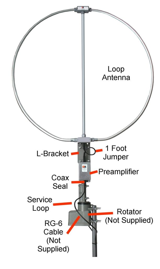
The following figure of the radiation pattern of the antenna shows the sharp, bidirectional null in the pattern. If carefully located and kept away from nearby conductors, the null depth can be 30 dB or even greater. The antenna’s symmetry ensures that both sides of the antenna are electrically balanced, helping prevent coupling to the main feed line that would reduce the null depth or distort the pattern. The antenna can be rotated to aim the null at a noise source or in the general direction of noise sources so that the desired signal is received with the best (highest) SNR.
You can build this type of loop yourself from a spare piece of hardline or even regular flexible large-diameter cable such as RG-213 or RG-11. The ARRL Antenna Book includes plans for a simple loop in the chapter on Receiving Antennas. ACØC has published a detailed article on creating a three-band set of concentric loops optimized for 160, 80, and 40 meters.
EWE
The basic EWE antenna is shown in the following figure. It was originally designed by Floyd Koontz, WA2WVL, and described in QST February 1995. (The name “EWE” refers to the upside-down U-shape of the antenna.) This antenna develops a unidirectional pattern from the relative phase difference between the two vertical elements (wires 1 and 3) of about 45 degrees. Wire 2 adds another 180 degrees of phase shift by reversing the current direction, so the total phase difference is about 135 degrees and the resulting cardioid pattern is shown below. The antenna receives vertically polarized signals best.
By choosing different sets of dimensions and termination (resistor) values, the antenna can be used over different frequency ranges. An 80 meter EWE over average ground with 10 foot vertical wires, a 25 foot top wire, and an 850 ohm termination resistor has a front-to-back ratio (F/B) of about 35 dB. The gain is –18 dBi so a 20 dB preamp is required. See the original article for detailed construction information.
Small Loops
Somewhat larger than the small coaxial loops, these antennas aren’t really “loops” in the sense that they have a uniform current around the entire antenna. These “small loops” act like a pair of phased verticals similar to the EWE, even if the antennas look like diamonds or triangles. Like the EWE, the horizontal components of the wire create the necessary phase shift between the vertical current components. (Current in a sloped conductor has both a horizontal and a vertical component.) W8JI provides a detailed description of how this family of antennas works on his website.
Resistive loads and conductor orientation create the uni-directional cardioid pattern. These antennas work best over good ground and also reject high-angle, horizontally polarized (NVIS) signals from relatively nearby stations. Like the EWE, there is enough cancellation between the currents, even of the desired signal, such that a preamplifier is required, typically 20 dB or more.
As discussed by W8JI, it is very important that the feed line not couple to the antenna, which would upset the phase relationship between the currents and reduce directivity. Running the feed line underground is a good way to minimize coupling and noise pickup. Matching transformers should be constructed to minimize inter-winding capacitance.
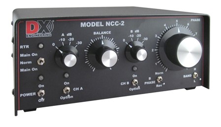
All of these antennas can be combined into arrays. The resulting pattern can be controlled by a phasing system such as the DX Engineering NCC-2 Receive Antenna Phasing Controller shown in the photo. Arrays of directive antennas separated by 1/4 wavelength or more can develop impressive radiation patterns with steerable nulls and other benefits. The NCC-2 also includes preamplifier modules.
K9AY Loop
The K9AY loop is very popular due to its small size and simple construction. It only requires one vertical support, typically about 25 feet high, so a tree or pole will do the job.
The basic antenna dimensions are shown in the following figure. Construction of the K9AY loop is straightforward and described in detail by its inventor on his website, including the details of the matching feed line transformer. This antenna will work well on 160 through 40 meters.
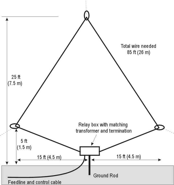
Because the feed point and terminating resistor are at the bottom-center of the antenna, it is easy to connect a DPDT relay to switch the wire ends and reverse the antenna pattern. A pair of K9AY loops at right angles on a single support can be switched to produce a four-direction pattern using a separate control cable or by sending different voltages on the feed line using bias tees. Numerous schematics for the switching controller are available online.
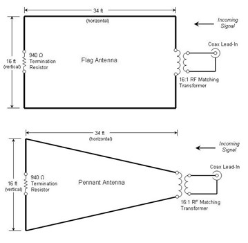
Flag and Pennant Antennas
A further refinement of the “small loop” idea, the flag and pennant antennas shown in the figure are based on the same arrangement of vertical currents and horizontal phasing lines. A compilation of articles and designs for these antennas is available online, including transformer design and other construction details. Performance is similar to a K9AY loop but because of the smaller size, additional preamplification is required and a 30 dB preamp is usually used.
VE3DO Loop
Somewhat bigger than the K9AY loop, the VE3DO loop is a larger variation of the flag antenna. You can find an excellent set of presentation slides by K9YC that go into detail about the antenna’s construction and topics associated with receiving antennas. The increased separation of the vertical current elements results in a somewhat better pattern than the K9AY loop. The antenna’s designer claims that the performance is often comparable to 1-wavelength Beverage antennas, although with considerable variability.