
The oldest radio antenna is—guess what—a dipole. In fact, a dipole was used by Professor Hertz to discover electromagnetic waves in 1886. How did he decide to use a dipole? After all, the first edition of the ARRL Antenna Book wasn’t printed for another 53 years!
As it turns out, a vibrating guitar string and a dipole have a lot in common. On their fundamental frequency, they are one-half wavelength long and very efficient at responding to and generating (or radiating) energy as sound or radio waves. Hertz “plucked” or excited his dipole with a spark and it radiated waves at around 70 MHz. An identical dipole across the lab picked up those waves and developed a small arc across its terminals, the first case of RFI!
Dipole Refresher
So useful and basic, the dipole is the building block for nearly all antennas used by amateurs in one form or another. With a feed line attached in the middle, it is easy to excite with electromagnetic energy and it receives signals just as well. The dipole delivers about the best “bang for the buck” in radio!
When the length of the dipole is ½ λ (one-half wavelength, with the Greek letter lambda, λ, being the symbol for wavelength), the dipole is resonant on its lowest or fundamental resonant frequency. At this frequency, the current on the dipole is all in the same direction but reverses its direction from one half-cycle to the next. Just flip the figure below horizontally around its center to see the dipole at work. The feed point impedance at the midpoint where current is high and voltage low is a good match to coaxial cable, as well.
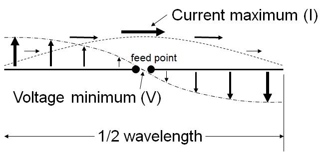
The current oscillating back and forth radiates energy away as radio waves that are strongest broadside to the current. This creates the familiar figure-8 pattern that shows the strength of the signal in various directions from a dipole being excited on its fundamental.
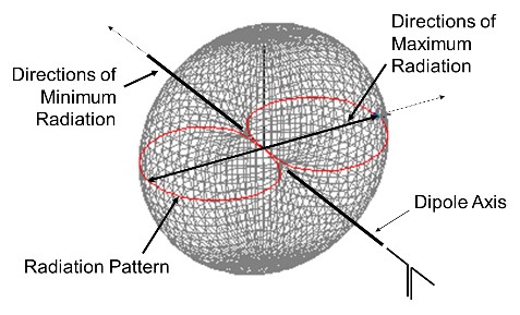
With more than one dipole radiating energy, the signals add and subtract, reinforcing the signal in some directions and canceling in others. This creates gain in some directions called lobes, and creates minima, or nulls, in others. By using the half-wave dipole as a building block, called an element,we can arrange the dipoles so they create some very useful patterns.
Many arrangements of dipoles were invented long before the rotatable beam, and several are still very popular today. Generally referred to as wire antennas, Hams love the various designs for their affordability and performance. We’ll explore a few common examples in terms of the dipole elements from which they are constructed.
Dipoles Used on Harmonics
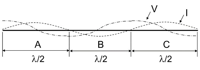
The simplest wire antenna beyond the half-wave dipole is to just use it on one of its odd harmonics. For example, a 40 meter dipole can be used on 15 meters, too. It’s like three half-wave dipoles connected together, end to end. As you can see in the figure, the “middle” dipole element (B) has its current maximum at the same point (but out of phase with A and C) so it provides a low SWR on that band, as well. (The resonant frequency is a little higher than three times the fundamental, but it’s still quite useable.) The pattern has a lot of lobes because the signals from the three end-to-end elements add and subtract at different angles.
The Extended Double Zepp and G5RV
Taking the end-to-end dipole a little further, we can make a great multi-band antenna. Start with a dipole fed at one end; this was originally known as the “Zepp” and today as the “End-Fed Half-Wave.” Then add a second dipole in line with and right next to it; this is a colinear array called the “Double Zepp.” If the two dipoles are fed with one feed line, they are out-of-phase so the radiation pattern looks like a cloverleaf. However, if you move the dipoles apart, the single broadside lobe can reappear.
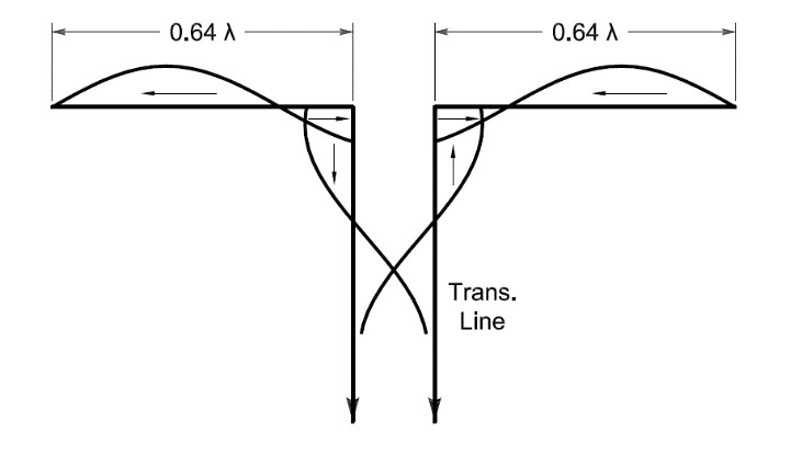
To feed the dipoles with one feed line so they are in-phase but separated, a center section is used—imagine our third-harmonic dipole with its center section pulled partially into a parallel-conductor feed line as shown in the figure below. If each side of the remaining antenna is about 5/8-λ long, this creates the “Extended Double Zepp” or EDZ. The length of the feed line also performs an interesting transmission line trick and creates a 50-ohm point where coax can be attached. With an antenna tuner, you can use this antenna as a dipole on the bands below the fundamental and as a colinear array of sorts on the higher bands.
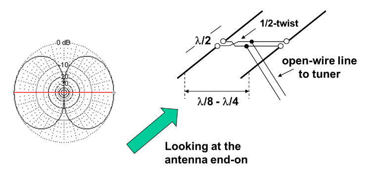
The 8JK Array
If the end-to-end dipoles create a multi-lobed pattern, what about dipoles arranged side-to-side? In fact, two dipoles close together can make a very useful pattern. Back in the 1930s, antenna designer and professor John Kraus, W8JK, knew that signals radiated at high vertical angles weren’t of much use for working DX, but that was where dipoles low to the ground radiated most of their signals. He came up with the bright idea to feed two horizontal dipoles with signals out-of-phase so that directly broadside to them—straight up—the radiated signals would cancel. The horizontal separation keeps the signals from canceling in plane of the dipoles, resulting in plenty of DX-friendly, low-angle radiation. This is called an endfire array because the maximum radiation of the antenna is in the plane of the elements.
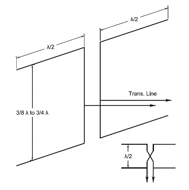
The Lazy H
The 8JK can be turned on its side, creating another useful and popular antenna, the Lazy H. As the figure shows, the plane of the dipole elements is vertical. This pair of dipoles is fed in-phase so the signals broadside to the array add together. Depending on the vertical separation, the signals partially cancel or, at ½-λ separation, completely cancel. The Lazy H requires higher vertical supports than the 8JK but is a great DX antenna. The Lazy H can be configured to perform consistently on several bands, as well. A pair of Lazy H’s at right angles to each other is a pretty effective antenna farm!
Full-Wave Loops
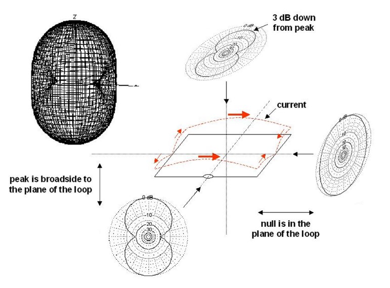
We can arrange dipoles in a line or put them side by side, but what if we hooked them up in a triangle or square? This arrangement creates the popular full-wave loop family of antennas. The simplest is made from two ½-λ dipoles bent so that their ends connect and make a square. This is the basic element used to make “quad” antennas. As long as the shape is symmetrical and open, such as a triangle or square or even curved into a circle, the pattern is about the same, radiating best broadside to the plane of the loop. The feed point impedance is higher than for a dipole—typically 120 ohms or so—making it a good candidate for a quarter-wave matching transformeror Q-section made from ¼-λ of feed line with the right characteristic impedance.
With the loop horizontal, on its fundamental the radiation is strongest straight up. These are sometimes referred to as “skywarmers” or “cloudburners” and are great for regional communications on the lower HF bands, such as emergency communication operating.
If the loop is longer than 1 λ, each side begins to act like multiple dipoles with radiation patterns having multiple lobes. The loop’s pattern adds all of those patterns from the individual sides to make a fairly complex but more-or-less omnidirectional pattern. That makes a large loop a good all-band, multi-purpose antenna, popular for Field Day and portable operation, as well.
Long Wires
Finally, you can just put up a piece of wire and apply power to it, without worrying about the pattern. These “random wire” antennas are usually fed at or near one end with low-loss parallel-conductor feed line and a tuner. If the wire length gets to be more than 1 λ, the antenna is in the “long wire” category. These are traveling-wave antennas. The longer the wire, the more the radiation is concentrated in both directions along the wire. By arranging a pair of long wires in a V so that the signals add together, a “Vee beam” is created. A pair of Vee beams back to back in a diamond shape creates the famous rhombic. These take up a lot of real estate and require tall supports but develop an excellent pattern for DX operation. In fact, the ARRL’s symbol is the rhombic’s diamond!
Resources
Obviously, I’ve just scratched the surface of what you can do with some wire and a little ingenuity. If you’d like to learn more about wire antennas, there is lots of material in the ARRL Antenna Book, as well as the ARRL’s three-volume Wire Antenna Classics and multi-volume Antenna Compendium series. The RSGB’s Practical Wire Antennas by G3BDQ is a great introduction to wire antennas. (It’s out of print but available used.) And you’re sure to enjoy the late W4RNL’s article “My Top Five Multi-Band Backyard Wire HF Antennas.”
The simple “wire-in-the-trees” is where radio got its start, and those “skyhooks” are still going strong today!
Graphics courtesy of the American Radio Relay League