
In the OnAllBands entry, “What is Ferrite, Anyway?” we discussed what ferrite is and what makes up a “mix.” We also explored how ferrite behaves at different frequencies.
Ferrite has two primary applications; “inductive” and “EMI suppression.” (EMI stands for electromagnetic interference.) Ferrite used as an inductor’s core can store and release energy very efficiently at high frequencies — these are inductive applications. Ferrite can also act like a resistor and dissipate energy as heat. This may not sound useful but if you are trying to block or get rid of unwanted RF which is creating EMI, referred to as suppression, it’s just what you need! Most ferrites have a frequency range over which they work best as an inductor and another range where they are resistive. Table 1 shows the ranges for several common ferrites used by hams.
Table 1 – Common Ferrite Mixes and Permeabilities
| Mix | Permeability (μ) | Inductive Range (MHz) | EMI Range (MHz) |
| 31 | 1500 | Not recommended | 1-300 |
| 43 | 850 | <10 | 25-300 |
| 52 | 250 | <20 | 200-1000 |
| 61 | 125 | <100 | 200-2000 |
| 75 | 5000 | <0.75 | <20 |
| 77 | 2000 | <3 | Not recommended |
Data is from the Fair-Rite catalog, 17th edition, colors are DX Engineering marking conventions
Ferrite As An Inductor
Ferrites are used for inductor and transformer cores in many different applications and frequencies. A low-loss inductive mix would be the kind of material to use in a switchmode power supply, an amplifier output power combiner, or as an impedance transformer for matching an antenna to a feed line. Mixes are available for inductive applications at several hundred kHz all the way to VHF. There is a tiny ferrite bead in the 300 to 75 W transformer connecting your FM receiver’s folded dipole to the type F receptacle on a home stereo receiver. And every switching power supply uses a ferrite-core inductor or transformer, for example converting 60 Hz ac to the 13.8 Vdc that powers your transceiver.
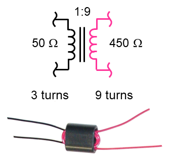
This figure shows a 9-to-1 impedance transformer for a receiving antenna such as a Beverage or K9AY loop. It uses a ferrite binocular core which is just like a regular one-hole bead but with two parallel holes. Each winding goes through both holes — one winding has 3 turns and the other has 9 turns but they aren’t connected directly together. The ferrite core is represented by the double lines between the winding symbols. The signal in one winding is converted to magnetic energy which is transferred through the ferrite to the other winding. This is called flux coupling where there is no direct connection from one winding to another.
Using Ferrite As a Resistor
Why, then, would you want to use a high-loss ferrite? In order to suppress or get rid of RF energy you don’t want! There are two reasons for wanting to suppress EMI — keeping RF out of something it shouldn’t get into and keeping RF inside something it shouldn’t get out of. This is a very common problem in ham radio, so it’s good to have these types of ferrite around. Fair-Rite makes quite a number of mixes and Table 1 shows the frequency ranges of several common mixes that are used for EMI suppression.
The term “EMI suppression” means that the ferrite is being used to keep RF out of something vulnerable to RF. It can also mean that the ferrite is keeping RF from escaping a piece of equipment where it would be radiated as an interfering signal or conducted to somewhere it shouldn’t be. Ferrite used in this way dissipates the RF energy as heat, just as a resistor. If we looked at the impedance ferrite creates on, say, a wire going through a ferrite bead, we’d find that it is mostly resistance.
One of the most important ham radio uses of ferrite components is as an RF choke. A choke can block RF current on feed lines and other station wiring. Ferrite chokes consist of a clamp-on core or a toroid with cables or wires wound on them. That lump at the end of a computer cable near the connector is a ferrite clamp-on or bead molded into the cable jacket. Figure 2 shows a typical assembly. The ferrite creates a resistance in the path of RF flowing along the outside of the cable shield. The bead in the photo keeps RF from escaping or getting into the USB jack.
In your amateur station, ferrite chokes are used primarily on antenna feed lines and on audio, control, and computer cables. You will find that there are connections in your station that seem to delight in picking up your transmitted signal. The resulting RFI can be pretty vexing! The same thing occurs for home entertainment systems and computer equipment when a cable makes a path for RF to get into a piece of equipment. A ferrite choke often works wonders to block that RF, too. Once you’ve identified which cable is the culprit, winding a few turns of the equipment end of the cable through a core with the right mix often stops the RF in its tracks. Remember that you have to use the right mix of ferrite for the frequencies of the current you’re trying to block.
A choke balun is the term for a ferrite choke used at the transition between a feed line and an antenna. The choke’s function is to block any RF current that would otherwise flow on the feed line, disrupting the antenna’s radiation pattern and changing the feed point impedance, too. Choke baluns are one of the most common uses of ferrite outside of the electronics themselves. We’ll cover them in another installment of OnAllBands.