
Transformers for Impedance Matching
One of a transformer’s important functions is impedance transformation. Impedance transformation is just changing the ratio of voltage-to-current in one winding to a different ratio of voltage-to-current. That’s the function of a 60 Hz power transformer as well as an RF “Unun”—they just change the ratio while losing as little of the power passing through them as possible.
Impedance-matching transformers are common in antenna systems. On the transmitting side, high-power transformers like the Maxi-Core® 9:1 model are used between 50-W feed lines and high-impedance antennas or parallel-conductor feed lines. On the receiving side, antennas are matched to 50 or 75 W feed lines with low-power units like the KD9SV SV-PEN transformers shown in the figure.
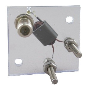
This miniature receiving antenna transformer (above) uses a binocular core with two parallel holes for the windings. The primary and secondary are wound on top of each other.
At audio frequencies, impedance-matching transformers are used when a low-impedance circuit, like a speaker or headphones, is connected to a high-impedance (such as 600 W) circuit output. Some transmitters are designed for a high-impedance microphone. If you want to use the typical low-impedance dynamic microphone, you’ll need a matching transformer like the Heil Sound XT-1.
Finally, at any frequency, you need to be sure the transformer meets its specifications over the necessary bandwidth and with plenty of margin or “overhead” at the signal power levels. For Ham radio, audio bandwidths covering at least 300-3,000 Hz are necessary. At RF, operating on HF for example, the transformer has to work from 30 MHz down to the lowest band on which you operate. Similar considerations apply at VHF and higher frequencies. Give yourself a two-times (2x) power factor, as well. Transformer cores, whether iron or ferrite, are inherently non-linear near their power-handling limits, which creates distortion, harmonics, and intermodulation. You’ve gone to a lot of trouble to create or receive clean signals—keep them that way!
Transformers for Isolation
Another important transformer function is isolation, also known as galvanic isolation, which means no direct electrical connection between the input and output. Isolation is needed when a connection between a power source and power-consuming device would be hazardous. An AC power transformer isolates the powered equipment from the AC line. Isolation is also used to prevent unwanted common-mode signals to get from, say, an antenna to a feed line or from a PC to a sensitive microphone input.
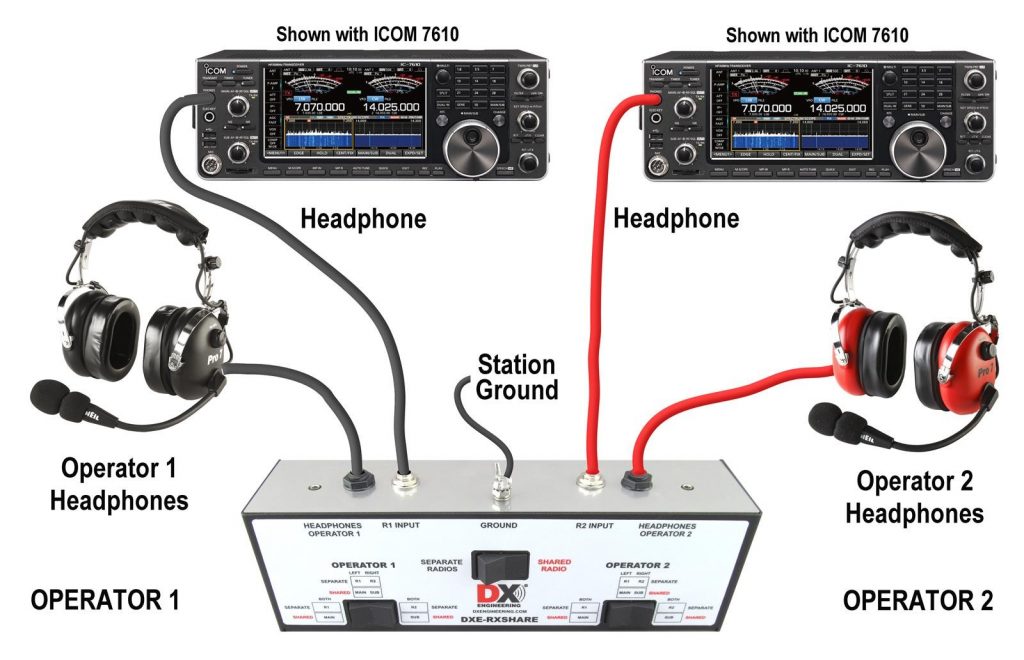
Trying to switch between or share audio from more than one piece of equipment is a good example of when isolation is necessary. If you build a headphone switch box to listen to audio from two different receivers, you’ll often find that leads to crosstalk. That means you can hear low-level Receiver A audio when listening to Receiver B. Crosstalk comes from the shared common connection between the receiver audio outputs. By using transformers, such as in the DX Engineering RXShare switching system shown below, the receiver audio outputs operate independently.
Hum and buzz can also be a problem, particularly when trying to connect a computer to a sensitive microphone input for operating on a digital mode. Interfaces such as the Rigblaster interfaces or the Unified Microsystems SCI-6 kit use a transformer in the audio signal lines going into and out of the PC sound card so there is no direct connection between the radio’s audio input circuits and the PC.
What’s the difference between hum and buzz? Hum is caused by a magnetic field creating a voltage in a conducting path. For example, a microphone cable placed close to a power transformer will probably add some hum to the speech signal. Hum usually sounds like a pure sine wave at the AC power frequency—a very low note at 60 Hz (in North America).
Buzz is caused by ripple on DC power that is caused by rectification of the AC input voltage. Buzz has a higher pitch than hum because full-wave rectified current pulses at 120 Hz. Buzz usually has a sharper sound because of the high harmonic content of the pulses. Buzz can also be caused by currents on an AC neutral conductor. Transformers break the conducting path that allows hum or buzz to flow in a connection between the equipment.