
A feed line RF choke creates a high impedance in the path of RF common-mode current on the outside surface of a coaxial cable shield. The choke doesn’t affect currents inside the coax, just on the outer surface. By blocking the current, the choke minimizes the effect of the feed line on antenna performance, reduces unwanted RF in a station or other equipment, and can prevent noise from getting into the antenna system.
When installed at an antenna feed point the choke is called a choke balun. This is because it forces all of the currents inside the feed line to divide equally between the antenna feed point terminals. That’s the function of a balun, to transfer power between a balanced system (the antenna) and an unbalanced system (the coaxial feed line). For more information about baluns, read the article “Baluns: What They Do and How They Do It” by Roy Lewallen, W7EL.
Note that feed line chokes are only possible with shielded coaxial cable. A choke cannot be created from parallel-conductor feed lines in this way because the internal RF field extends beyond the conductors. This article does not cover resonant chokes or baluns that use tuned sections of coax or other structures to create a high impedance on a feed line.
Why Is a Choke Needed?
There are several common situations in which a choke is recommended. In order of lowest to highest required impedance:
- Decouple a coaxial cable shield at an antenna feed point
- Pattern preservation to lower received noise and interference
- Reduce RFI in the station and to home equipment caused by common-mode current
- Block noise from getting into the coax at a feed point or other equipment
For basic decoupling to minimize the feed line’s outer surface interaction with the antenna, a rule-of-thumb is that 10 times the feed point impedance is sufficient. If the feed point impedance is 50Ω, then a 500-Ω choke would be required. This also assumes that the feed line is oriented symmetrically with respect to a balanced antenna so that currents coupled to the feed line tend to cancel. If the feed point is not balanced or the feed line is asymmetrically oriented in some way, more impedance may be required.
A choke balun at the feed point keeps feed line interaction from filling in an antenna pattern’s nulls through re-radiation from common-mode current. That means the antenna will receive less noise and interfering signals from sources away from the main lobe. Be prepared to model and experiment to find out how much impedance is needed to meet your needs.
Reducing feed line current suppresses RFI from current getting into equipment. RFI suppression may be more responsive to choke placement than high impedance, so be prepared to try chokes at different places along the feed line. A choke at the point where the cables enter a building is often helpful. Ferrite core chokes in the station are often helpful as well.
The most difficult task for a choke, especially at VHF, is to keep noise and interference picked up on the feed line shield from getting inside the cable at a feed point or other equipment. The currents are very small, and receivers are very sensitive, so as much as 5 kΩ choking impedance may be required. Lower impedance (and expense) may be sufficient if you are willing to experiment.
If you are adding a feed line choke for “good practice” and not because of any special need, you can stay with the simpler designs. As power level and impedance needs increase, consider using the higher-performance chokes. We’ll describe five different types of feed line chokes, beginning with a simple coil of coax. (For a more in-depth treatment of feed line chokes, see Chapter 24 – Transmission Line System Techniques in recent editions of the ARRL Antenna Book.)
Scramble-Wound Coax Choke
The scramble-wound choke couldn’t be easier: coil up some coax just like a coil of rope, secure the windings with electrical tape, and you’re done. These chokes are easy to make and apply for temporary installations. The photo below, found in many editions of the ARRL Antenna Book and ARRL Handbook, illustrates the basic idea. The end of the cable is formed into leads attached to the antenna and the coil is formed, secured, and suspended from the feed point insulator or antenna boom.
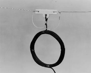
(Photo courtesy of the American Radio Relay League)
The parasitic capacitance between turns interacting with the inductance of the cable shield’s outer surface creates a parallel-LC circuit that is self-resonant. This choke can create a few hundred ohms of reactive impedance but only on bands where it is close to self-resonance. Below self-resonance, the choke’s reactance gets lower with decreasing frequency. Above self-resonance, the choke is capacitive, and reactance gets lower with increasing frequency, too.
It is also difficult to guarantee consistent performance of a scramble-wound choke because of the semi-random way in which the turns are oriented and held together. This changes the characteristics of the coil and the frequency range where it works as intended. No two scramble-wound chokes are exactly the same, so don’t use this approach if you need them to be identical or high-performance.
This and the following tables, based on more comprehensive tables in the ARRL Antenna Book, suggest some common variations that generally work over the ranges given. The table gives a frequency range, the approximate length of cable, and how many turns are needed which determines the diameter of the coil.
Scramble-Wound Chokes
Freq (MHz) RG-58 or RG-213
1.8-3.5 40 feet, 20 turns
3.5-10 18 feet, 9-10 turns
14-30 8 feet, 6-7 turns
Mechanically, the cable is stressed at three points: where it is wrapped around or through a center insulator, where the cable supports the coil, and where the coil supports the cable between the antenna and the ground or other support. The sharp bend and weight will eventually cause a short circuit between the center conductor and shield unless additional support is provided. Use light rope or nylon strap to support the coil and feed line in some other way. Leave an inch or two between a metal antenna boom and the coil. For temporary use, though, the technique in the photo is fine for RG-8X or smaller cables, while thicker cables need more support.
Single-Layer Coax Choke
The single-layer, or solenoidal,choke is much like a scramble-wound choke but only has a single layer with the turns next to each other. These two photos show typical examples. In the top photo, a scramble-wound coil is converted to a single-layer by arranging the turns side-by-side and using cable ties to hold them in place. This generally only works well for small chokes with a few turns because it is difficult to support more turns in a way that does not let them move.
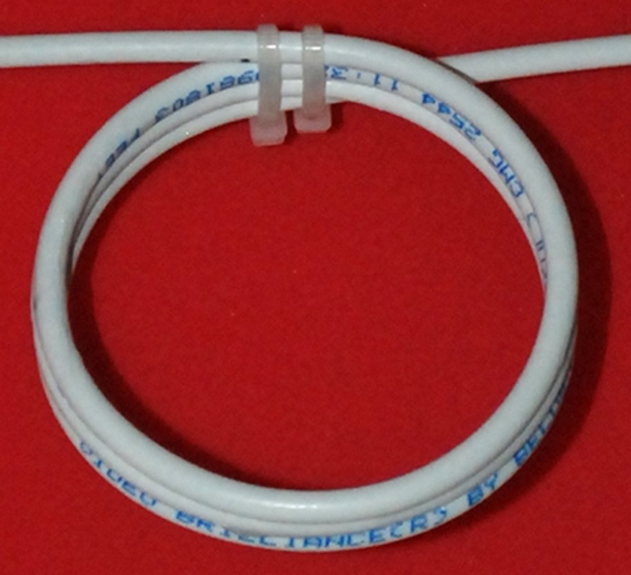
(Photo by K6STI from ham-radio.com/k6sti/balun.htm)
The second example below is more typical of a single-layer choke. A non-conducting cylindrical form such as PVC or fiberglass holds the turns in place and provides mechanical support. Note in this design that cable bends are gradual, secured by cable ties to the form.
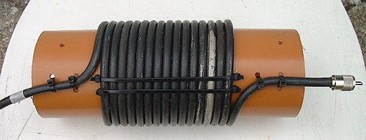
(Photo by PF9Z from pf9z.com/rf-choke-build-your-own/)
These chokes exhibit self-resonance just like scramble-wound chokes, but their performance is more consistent and predictable. The self-resonant frequency is generally higher since the parasitic capacitance between turns is reduced. These chokes are also much heavier than scramble-wound chokes, requiring sturdy supports at the antenna or wherever they are used. The following table shows sample designs for single-layer chokes made from RG-213.
Multiple Band, Single-Layer Solenoid
Freq (MHz) RG-213
7-24 12 turns, 4 1/4″ diameter
7-24 8 turns, 6 5/8″ diameter
14-30 6 turns, 4 1/4″ diameter
Ferrite-Core Coiled-Coax Chokes
Wound-coax chokes are inexpensive but do not have broadband performance. They are best over one or two bands, and their choking impedance is reduced outside the favored range. To obtain broadband performance, the coax is wound on a toroid core or through a large ferrite clamp-on bead. For a good introduction to using ferrite see Jim Brown, K9YC’s tutorial “A Ham’s Guide to RFI, Ferrites, Baluns, and Audio Interfacing.”
This type of construction is shown in the following photo. The impedance of these chokes is equal to the impedance of one turn of cable through core, multiplied by the number of turns, times the number of cores. For example, if one turn through one core provides 100Ω, then five turns through three cores creates 100 x 5 x 3 = 1,500Ω.
(Photo from www.pa0nhc.nl/CommonModeChokes/indexE.htm)
The following table shows several useful examples of ferrite-core coiled-coax chokes using both RG-213 and RG-8X cables that use solid polyethylene (PE) center insulation. The core is a 2.4-inch O.D., 1.4-inch I.D. toroid unless specified as a “Big clamp-on,” which refers to a 1-inch I.D., 1.125-inch-long clamp-on bead. Turn diameter for chokes in the table should be approximately 6 inches. Below 10 MHz, use #31 mix ferrite. From 10-30 MHz, #31 or #43 mix can be used. Above 30 MHz, use #43 mix.
Wound-Coax Chokes on Ferrite Cores
| Frequency Band(s) Mix (MHz) | Mix | RG-213 Turns | Cores | RG-8X Turns | Cores | Note |
|---|---|---|---|---|---|---|
| 3.5-7 | #31 | 6 | 5 | 7 | 4 | |
| 7-14 | #31 or #43 | 5 | 5 | 8 | Big clamp-on | |
| 14-28 | #31 or #43 | 4 | 1 | Big Clamp-On | Two chokes in series | |
| 14-28 | #31 or #43 | 4 | 6 |
Wound-Coax Toroid-Core Chokes
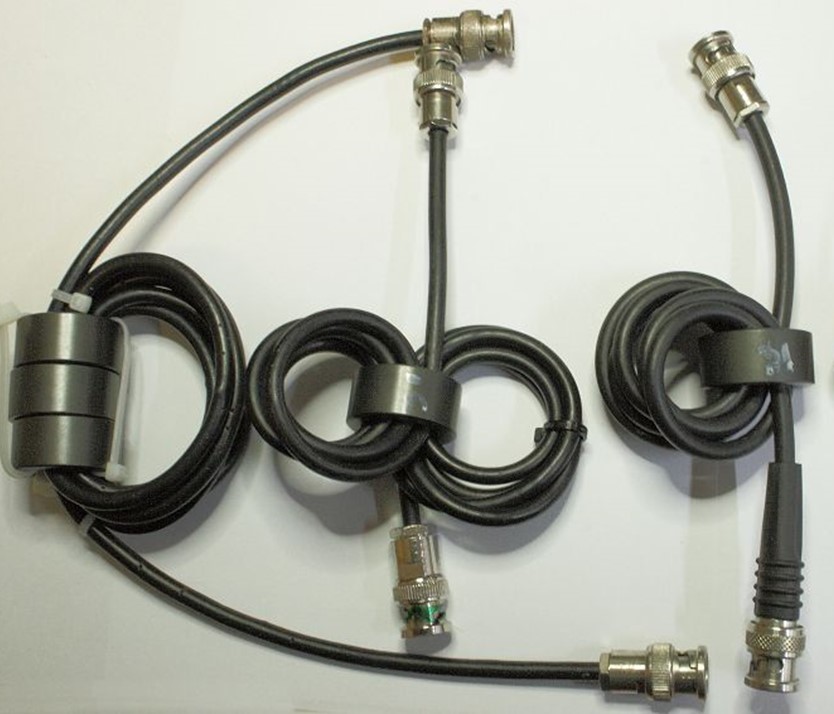
Even better performance with a single core can be obtained by winding high-performance TFE (Teflon-insulated) coax or parallel-wire transmission line on a toroid. The recommended coax is RG-400, which is fairly expensive per foot but not a lot of it is required to construct a choke. High impedance is obtained with just a single 2.4-inch O.D. ferrite core, and multiple chokes in series gives really excellent performance. The photos show a pair of chokes, the first wound with RG-400 and the second with parallel-wire transmission line. Detailed instructions for creating these chokes is available in the ARRL Antenna Book.
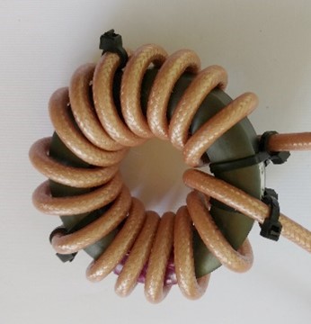
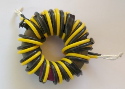
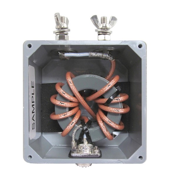
The preceding and following photos are from the excellent tutorial Coaxial Transmitting Chokes by K9YC and Glen Brown, W6GJB. These chokes can be placed in an enclosure with coaxial connectors or supported on an insulating board as in the following photo, showing a feed point balun for a dipole or other wire antenna. The tutorial provides an enormous amount of detail about the design, construction, and performance of these chokes, which are state of the art for amateurs.
A number of manufacturers produce this type of feed line choke balun, such as the DX Engineering DXE-MC20-FC shown in the following photo, which uses a stack of two ferrite cores.
Ferrite Bead Chokes
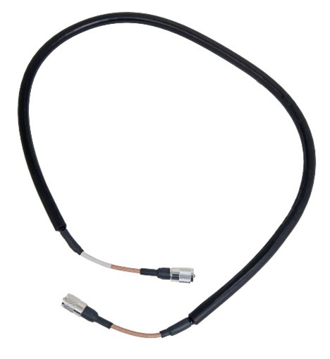
Instead of winding multiple turns of cable on a toroid core, a choke can also be created by placing multiple small beads on a length of coax. This creates what is sometimes called a bead balun, originally described in the amateur radio world by Walt Maxwell, W2DU. Similar to the wound-coax versions, the total impedance equals the impedance created by one bead times the number of beads used. The photo shows a Comtek COM-CFC-50A feed line choke, using 75 beads on high-performance PTFE RG-400 coax.
Practical Concerns
When constructing feed line chokes, there are a number of mechanical and design aspects to consider so the choke provides good performance for a long time.
- Supporting the choke: The extra weight of a choke or choke balun can lead to mechanical failures as the choke moves in the wind or simply pulls on the connections. Be sure to support the choke so that no connectors or connections are mechanically stressed.
- Keep away from metal: Keep chokes away from metal surfaces, such as towers, masts, and antenna booms. A separation of an inch or two is sufficient to prevent capacitive coupling that alters the choke’s performance. Plastic standoffs are often used to hold the chokes.
- Foam core cable: Only use solid-insulation (PE or PTFE) coaxial cable. Do not use foam-insulation cable. Over time, heating and mechanical stress will induce the center conductor to slowly migrate through the insulation, changing the characteristic impedance of the cable and often resulting in a short circuit.
- Minimum bend radius: Do not wind PE-insulation cables such as RG-213 tightly on a radius smaller than a few inches. The same center conductor migration problem that happens with foam insulation will gradually occur. PTFE-insulation cable, on the other hand, may be tightly wound but must not be repeatedly flexed or bent at sharp angles.
- High power: If you are running high power, a ferrite choke may be subjected to voltages high enough to cause heating and possibly fracture. (See the July 2015 QST article “Don’t Blow Up Your Balun!” by Dean Straw, N6BV, for more about baluns and high power.) Be sure to give your choke enough ventilation to avoid overheating. If necessary, use extra chokes in series to reduce common-mode voltage and current at the choke.