
After the previous couple of articles about troubleshooting (“Maintaining and Troubleshooting an HF Station” and “Troubleshooting Your Transceiver”), it’s time to move outside the station. An antenna system may not have a lot of moving parts or complicated electronics, but it’s a critical part of your station, and exposure to sunlight, precipitation, and wind can cause problems. Let’s check it out…
How Do You Know It’s the Antenna System?
If you think you have a problem, how do you know it’s in the antenna system? By antenna system, I mean everything from the feed line connector on the back of your radio all the way to where the radio waves leave your antenna. Good troubleshooting technique means carefully checking each piece of equipment to be sure it’s functioning correctly before assuming something else is at fault. So before we move on, confirm that your transceiver…
- Transmits OK connected to a dummy load with a known-good coax jumper
- Receives signal with a temporary antenna or piece of wire connected
- Is configured to use the “right” antenna
Further, make sure any software that controls antenna system functions is configured and running OK.
It’s funny how often just checking those basic functions turns up a simple problem disguised as a “bad antenna.” In the words of Homer Simpson, “Doh!” So double-check everything one last time.
You might want to review the operation of your antennas and equipment, like tuners and switches, as well. Commercial models will come with a user’s manual and, for equipment, a schematic. Be sure you know how the equipment is supposed to work and that you’re using it correctly before assuming there is a problem. (I once caused myself a lot of grief by assuming a “Bypass” function worked in a way it really didn’t…then I read the manual!) The whole point is to be sure you really know what you think you know before starting the process. If you have a recent edition of the ARRL Antenna Book, there is a whole chapter on troubleshooting and maintenance with helpful tips.
Describe the Problem
Are you sure you have a clear understanding of what the problem is? Some are simple (infinite SWR on all bands) and some are subtle (minimum SWR on 15 meters is 200 kHz too high). Some are always there but others might change with time (SWR increases after a few minutes of operation) or come and go (SWR jumps to infinite occasionally). Try to capture any clues associated with the problem.
Now, write it down! Take careful measurements, like an SWR sweep on the troublesome band, or record what symptoms you notice when the problem is present. If you have measurements from before the problem appeared, review those. If possible problems come to mind, write them down as well, but try not to jump to conclusions—you can waste a lot of time chasing a problem that doesn’t exist.
Get Your Test Equipment Ready
Now it’s time to collect all the necessary “stuff” needed to troubleshoot your “stuff.” The best gadget ever invented for Ham radio antenna system work is the antenna analyzer. Since you can’t see radio waves interacting with your antenna, measuring impedance either at the feed point or through a feed line is pretty much your only option.
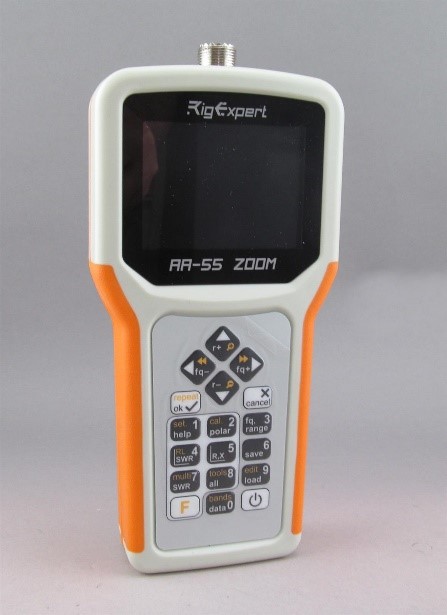
An SWR bridge will do if you don’t have anything else, but an analyzer gives you so much more information and doesn’t require transmitting a signal on the air. The new handheld models, like the RigExpert line, will not only measure the impedance at different frequencies but graph it for you while taking the measurement. This makes tuning up a matching network easy and gives you a good picture into frequency-related behavior, which is very important in testing and troubleshooting. Some analyzers will record and save the data as a downloadable file for you to work with on a PC. Most manufacturers also offer a protective carry pouch for use in the field, or you can choose a case specifically paired with the analyzer model.
What Other Equipment and Tools?
- A lightweight voltmeter—check the battery! (Write down your rotator’s normal terminal-to-terminal resistances for checking at the rotator.)
- A known-good coax jumper (3 to 10 feet) and a couple of PL-258 “barrel” connectors to bypass a piece of equipment
- Two pairs of slip-jaw pliers to tighten or loosen screw-on connectors like PL-259s, and a small adjustable wrench
- Phillips and flat-blade screwdrivers
- A small steel or brass bristle brush for removing dirt or corrosion
- Ratchet and 7/16″, 1/2″, and 5/8″ deep-well sockets for U-bolts and mast clamps
- A utility knife and good quality electrical tape to remove or replace waterproofing
- A small measuring tape to check lengths
- A small tube of anti-oxidation compound like Penetrox and a shop rag to get it off your fingers

All of this will fit comfortably in a belt-mounted tool pouch. I leave most of this in a spare tool bag ready to go and do a quick checklist count before heading outside. Even if you don’t think you need some of this for the problem at hand, you can check other things or fix problems you notice while working.
Take a Good Look
Before getting into electrical measurements, it’s time for a “walk-through” inspection. Start at the back of your transceiver and work your way along the feed lines. Check that connectors are tightly attached to the equipment and that the coax is properly installed in them. There should be no corrosion or moisture inside the connector at all. Check carefully at any feed-through to outside the building. Condensation can form on either side of the connector due to temperature differences, and it can work its way inside connectors or corrode the point of contact between the connector and any metal panels or enclosures.
Unscrew the shell of soldered PL-259s so you can see the soldered connection—they ARE soldered, aren’t they? For crimped connectors, be sure the crimp is tight and holds the braid tightly in place. It’s helpful to have the receiver on and turned up so you can hear the telltale crackle of a loose connection when you wiggle a feed line or connector.
If everything inside is ship-shape, head outside and take a good look. A small pair of binoculars makes inspecting from ground level a lot easier. Are ropes and other supports as they should be? Look for weather-related damage, especially if there was severe weather before the problem appeared. Has anything sagged or drooped? Is something touching an antenna like a branch or wire? Inspect feed line connections carefully, making sure connectors are tight, clean, and dry—whether coax or open-wire line. This would be a good time to look for chafing damage where a rope goes over a branch or where a feed line wraps around a rotating mast.
While tower inspection and maintenance are beyond the scope of this article, any Ham with a tower should perform regular inspections to avoid problems. Two great books are available, each with a full chapter on what to look for and how to maintain a tower system: Antenna Towers for Radio Amateurs by Don Daso, K4ZA, and Up the Tower, by Steve Morris, K7LXC. Both are good to have before you start to climb.

For wire antennas, look for signs of mechanical stress or repeated flexing wherever the wire is secured to a support, insulator, or feed line. A center or in-line insulator supporting a heavy feed line puts stress on the feed line and the connections to the antenna. Check the waterproofing at the end of a coaxial feed line if pigtails are used to connect it to the antenna.
Help from a Friend
Having someone to give you a hand can be very helpful when checking antennas, particularly if they also have a Ham license and understand what you’re looking for and measuring. After all, the antennas are “out there” while your equipment is mostly “in there.” It’s hard to wiggle or turn something and then run back inside to see if that affects the antenna! A friend can provide helpful and alternative suggestions, too. Have them bring a handheld radio to coordinate tests and measurements.
Start from Either End
Everything looks OK but check that problem one more time. Still there? OK, get out the antenna analyzer. I’m assuming you own or have borrowed one, whether it is the analog meter type or one with a digital display. The process is straightforward: Disconnect the feed line from equipment and reconnect it to the analyzer. Take your measurement. If the impedance is as you expect, reconnect the feed line and move to the next connection in the system.
Let’s say you have a wire dipole. You lowered it and all of the mechanical details look OK, including the feed line connection at the feed point. Measure impedance at the closest point to the antenna where you can connect the analyzer. If impedance is OK, reconnect the cable and move to the next farther point in the system where you can measure SWR. Don’t re-waterproof any connections until you are done working—write down which connections will need to be waterproofed so you don’t forget later. Keep going until you get to a point where the problem appears. The cause is between the current and previous point of testing, whether it is in a cable, connector, or piece of equipment.
Intermittent problems are often a defective mechanical connection or something rubbing on or too close to an antenna. Assuming the close-up visual inspection was OK, with the antenna in place, tap on the antenna or wiggle the support while watching (or having your friend watch) the analyzer for jumpy readings. Gradually work your way back toward the measuring point until you find something loose or erratic. Remember that even with power as low as 100 watts, there are high voltages on antennas that can arc to nearby leaves or branches.
Problems that show up only after you’ve been transmitting for a while are usually a burned or oxidized contact in a connector, switch, or relay. Water in a connector can also create that “SWR-goes-up-after-I-transmit-for-a-while” symptom. A “dead” antenna that comes back to life after a quick “dit” or short transmission often has a bad relay or switch contact somewhere in the line. The short pulse of current is enough to punch through any film of corrosion or oxidation for a while. Another possible problem is a balun or impedance transformer with a core that has been overheated or cracked. These are often sealed, making internal inspection difficult, but you can put a resistor or dummy load across their output terminals and make impedance checks that way. A cracked core will often make rattling noises when the housing is shaken.
After the Problem is Found
Once you have solved the problem, re-waterproofed the connections, tightened the bolts, and put the equipment back in place, now it’s time to write down what you’ve learned. Note what the problem was and how you repaired it, anything special about the repair, tools you wish you’d had or supplies you need to replace, and suggestions for future installations. These stories make great articles in club newsletters and help others learn from your experiences. And finally, take a complete set of measurements so you can tell what “normal” is for next time!