In my previous article, I discussed overload from broadcast stations and the filters that could block those strong signals from getting to your radio. In this article, I’ll illustrate a few ways to make simple filters using nothing but sections of coaxial transmission lines.
What Is A Stub?
A stub is just a length of transmission line terminated in a fixed impedance, usually a short or open-circuit. The transmission line can be coax, open-wire, waveguide, etc., but in this article, we’ll be referring to coaxial cable. Single stubs can be used by themselves or in parallel with another transmission line to create a filtering effect.
Stub filter design utilizes three fundamental transmission line behaviors:
- Waves in a transmission line travel slower than in free space, so the physical length of
the transmission line is always shorter than its electrical length. For example, if a piece of RG-58 is 1-wavelength (1λ) long to energy traveling through it, the cable’s physical length will be about
two-thirds as long as the wavelength of the same energy traveling in free space. - Impedances in a transmission line repeat every ½-λ along the line. If I terminate a transmission line with a load whose impedance is 100 ohms at some frequency, f, then every ½-λ along
the line from that load, the transmission line will again present a 100-ohm impedance. - Open and short-circuits reflect 100% of the incident wave’s energy in a transmission line. For an open-circuit, the voltages of the incident and reflected waves are in phase and add together. The incident and reflected currents are out-of-phase and cancel so that there is zero current at the open-circuit. For a short-circuit, voltages cancel and currents add.
In this article, we’ll only consider two basic types of stubs: open and shorted. Stubs are referred to by their electrical length and terminating impedance. The electrical length of a stub, L, is generally given in terms of wavelengths: quarter-wave, half-wave, and so forth. Note that for a coaxial cable stub, the length includes the cable and any connectors.

How Does a Stub Create a Filter?
Stubs are used as filters by creating a short- or open-circuit at a specific frequency. The stub is then placed in a signal path to either pass or remove signals of that frequency.
The left-hand figure below illustrates how a ¼-λ open stub creates an apparent short-circuit. Imagine a single packet of RF energy just a few cycles long—a very short CW dit. The RF wave travels in the line from the transmitter, encountering the junction of the stub and the rest of the line. The wave divides 50-50 between the line and stub at that point (1). The wave traveling down the stub is phase shifted by 90 degrees because the stub is an electrical ¼-λ long (2). At the open-circuit, the incident wave is reflected with no phase shift (3). The reflected wave gets another 90 degrees of phase shift returning to the junction (4) for a total phase shift of 180 degrees. At the junction, the out-of-phase waves cancel, creating an apparent short-circuit (5). The quarter-wave open stub presents a short-circuit at its free end!
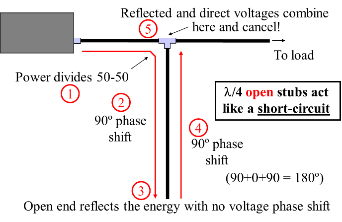
Complete cancelation only occurs if the stub is completely lossless and exactly ¼-λ long. Loss reduces the out-of-phase wave, preventing a complete cancelation. Being off-frequency means that the net phase shift won’t be precisely 180 degrees. Nevertheless, the range of frequencies over which most of the waves cancel is sufficient to be useful across a ham band. We just created a band-stop filter!
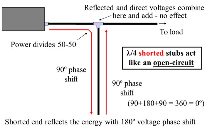
What happens if the stub is shorted, instead of open, as in the right-hand figure above? At the short, the incident wave is reflected with voltage shifted by 180 degrees instead of zero, making the total phase shift 360 degrees. The waves that originally split 50-50 now add back together, as if no stub was connected at all. The quarter-wave shorted stub acts like an open-circuit at its free end.
If our quarter-wave stub is doubled in physical length, it becomes a half-wave stub and the open- or short-circuit repeats at the free end. Doubling the frequency (halving the wavelength) without changing the physical length has exactly the same effect. As a result, a shorted stub that presents an open-circuit at its ¼-λ fundamental frequency, f, presents a short-circuit at its ½-λ second harmonic, 2f.
Using Filter Stubs
By far the most common application of a stub is to act as a filter for transmitter harmonics. The free end of a ¼-λ shorted stub also presents a short-circuit at the fourth, sixth, eighth, etc. harmonics where it is an integral number of half ½-wavelengths long. While passing energy at the fundamental frequency untouched, all even harmonics are canceled.
½-λ stubs also filter harmonics, but in a slightly different manner. The free end of a shorted ½-λ stub presents an open-circuit at one-half its fundamental frequency because at that frequency it is a ¼-λ stub. The stub acts like a short-circuit at the frequency for which it is a ½-λ stub and at all harmonics.
The table below lists the filtering effect of ¼ and ½-λ stubs cut for different ham bands. The possibilities are endless! Remember that to filter a transmitted signal, the stub (or filter) must be attached at the transmitter output. Harmonics and phase noise must be filtered at the source! Once transmitted, they are like any other signal and can’t be filtered out.
Useful ¼ and ½-λ Filter Stubs | ||
| Stub Type | Passes | Nulls |
¼-λ 160m shorted | 160 | 80,40,20,15,10 |
¼-λ 80m shorted | 80 | 40,20,15,10 |
¼-λ 80m open | 40,20 | 80 |
¼-λ 40m shorted | 40,15 | 20,10 |
| ¼-l 40m open | 20,10 | 40,15 |
¼-λ 20m shorted | 20 | 10 |
¼-λ 20m open | 10 | 20 |
The 60, 30, 17, and 12-meter bands are absent from the table because stubs cut to pass or null these bands don’t have a similar response in any of the other HF bands. These bands are not harmonically-related to other bands.
Stubs are also widely used as filters on the VHF and UHF bands, too. To minimize loss in the stub and increase harmonic rejection, use low-loss hardline for the stub. Since the wavelengths are shorter, the stubs are, too.
Most antenna analyzers have one or more functions that can show you the resonant frequency and electrical length of a stub. Look in the manual for instructions on how to use your analyzer this way. Velocity of propagation may vary from published values which will move the resonant frequency. It is best to start with your stub cut a little long and use an analyzer to tune the stub exactly. Remember to include the connector and any switches or adaptors when tuning.
Field Day Stub
Stub filters can come in really handy at multi-station Field Days. Transmitters are close together and the transmitted harmonics and phase noise can really be aggravating. This simple “Field Day Stub” design can help everybody get along!
The stub is ¼-λ long on 40 meters. (The length is typical of RG-58A/U solid polyethylene dielectric coax.) The switch changes the stub between shorted and open. A miniature toggle switch will suffice for 100–200 watt power levels. Changing from short to open switches the harmonic null from 20 and 10 meters to 40 and 15 meters. When you tune the stub, aim for ¼-λ resonance on 7.075 MHz so the harmonic frequencies are 14.150, 21.225, and 28.300 MHz.
Stubs and Inter-station Interference
You’ll find a lot more information about stubs in the ARRL’s Antenna Book, but the best reference for amateurs is George Cutsogeorge, W2VJN’s “Managing Interstation Interference.” Now in its second edition, it is packed with good information about how interference is generated, the use of stubs, filter selection, and other practical information for the station builder.