
It’s common to experience interference from a nearby broadcast station, including commercial and public safety transmitters. The usual symptom is a continuous stream of distorted audio on all channels or across a wide range of frequencies. Your received signal strength meter will probably show a full-scale reading, too. The interference will be present whenever the transmitter is on, and for broadcast stations, that is all the time. Interference can also be intermittent if the transmitter is turned on and off, such as for police or fire dispatch stations. This is pretty aggravating!
If you experience the interference while driving around, you can always move away from the source. If you live near the station or are trying to operate from high spots with lots of transmitters, though, you’ll have to take sterner measures.
What Is Overload and What Causes It?
Several types of interference are referred to as “overload.” The type of interference I’m writing about is a strong signal that travels through the normal signal path from the antenna system into the receiver circuitry. It is so strong that a circuit in the receiver is unable to process the signal as intended. This is usually a mixer, an RF amplifier or a filter. In a direct-sampling SDR that doesn’t have front-end analog circuits, receiver overload occurs when the analog-to-digital converter’s range is exceeded.
The result of overload can be distortion products that flood subsequent stages, covering up desired signals. Or the receiver’s gain control circuits are fooled into reducing gain until no signals can be heard. This is also referred to as “de-sense,” short for “desensitization.” Overload can occur in both AM receivers (which include SSB, CW, and FSK) and FM receivers.
What Sounds Like Overload, but Isn’t?
Once you are sure the problem is overload, there are several good remedies. But what if the problem isn’t overload? Here are some issues that act like an overload, but aren’t:
- Common-mode “breakthrough”—Your station’s cables act as antennas, picking up signals as common-mode current. When this current gets into a receiver (or any other piece of equipment), it will be amplified and processed, interfering with other signals that follow the normal path. Common-mode signals can be blocked by good shielding and ferrite RF chokes on the cables picking up the signals.
- External Intermodulation (IMD)—Strong signals can mix together in any non-linear circuit or device, including rectifiers accidentally created from corroded or rusty metal-to-metal contacts and bad antenna or cable connections outside. IMD products are generated on specific combinations of the strong signal frequencies, and when both signals aren’t present, the interfering product goes away.
- Diode harmonic generators—It only takes one strong signal to create harmonics in a rectifying junction. The diode can be outside (like corrosion) or inside your station. Common-mode RF current on rotator cables, relay control wiring, power supply wiring, speaker cables, etc. can get to unbypassed diodes or transistor junctions where harmonics are generated. The harmonic signals flow back along the same cables and are radiated like any other signal. Like IMD products, the harmonics are on specific frequencies.
- Transmitted IMD—Another form of IMD, splatter can be generated by an AM or SSB transmitter. Somewhere in the signal processing path, a stage is overdriven or misadjusted to create excessive levels of distortion. The resulting distortion products are transmitted like the desired signal and can cover a lot frequencies, especially for voice signals that themselves contain many different frequencies. Multiple simultaneous tones in an FSK signal can also create IMD products in the transmitted signal at combinations of the tone frequencies. Overdeviation from an FM transmitter also creates sidebands that create interference on nearby channels. These may sound like overload but are present whether the misadjusted signal is strong or weak.
Receiver Adjustments
A receiver can also be configured so that it overloads too easily, creating interference from strong signals all by itself. The receiver’s “front end” circuits—preamplifier, RF amplifiers, and mixer—are particularly susceptible. As mentioned earlier, a direct-sampling SDR can also overload when converting the signal to digital form. A clue that the interference is due to receiver overload is the threshold effect. As signal strength is reduced or gain is reduced below some threshold, the interference quickly disappears.
Turning off front-end gain stages is a first step to eliminating overload. If you have a receiver with an analog noise blanker (NB), it can be confused by strong signals and try to mute the receiver, creating distortion that sounds very much like splatter because it follows the same pattern as signal peaks. Turn off the noise blanker, too!
The ARRL Handbook explains receiver overload and includes a chapter on filters to help prevent overload.
Another way to reduce receiver gain is to turn on the attenuator if the receiver has one. (Some FM transceivers have an attenuator that is activated when RF Gain is turned down.) The RF Gain control may not control front-end gain but try reducing it as well. Your receiver may have a preselector—a tunable filter to reduce out-of-band signals, like those from broadcast stations.
All of these adjustments enable you to manage the gain of your receiver and make it harder to overload. Experiment with them to learn how they work. On the HF bands at and below 21 MHz, preamplification is rarely necessary—if you can hear an increase in noise when you connect the antenna, you don’t need a preamp. On the VHF bands, only use the preamp when you are trying to copy a very weak signal. Using the least amount of gain will reduce the noise your ears have to contend with under normal conditions, improving signal copy-ability and reducing listening fatigue.
Filters for AM BC Rejection
If you are convinced the overloading station’s signal is too powerful for your receiver to reject, it’s time for an external filter. The goal of using the external filter is to reduce the signal to a level that your receiver can manage without overloading. There are three basic types of filters to reject AM BC (broadcast) signals:
- Wave traps—Series LC circuits with an adjustable capacitor present a short circuit at their resonant frequency. These notch filters remove signals from a small range of frequencies. They are used when only one station’s signal needs to be filtered out.
- A high-pass broadcast reject (BC reject) filter rejects signals below 3.5 or 1.8 MHz. These also block signals in the 630 meter and 2200 meter bands. Because the AM BC band is close to the bottom of 160 meters, the filter rolloff slope needs to be steep, requiring a multi-section filter as described in my QST Hands-On Radio column, “Designing a Broadcast Reject Filter,” available in ARRL’s Hands-On Radio Experiments Volume 3.
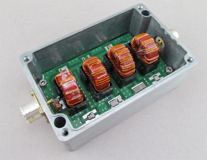
- Most BC-reject filters are receive-only, meaning their components are not rated for transmitted signal levels. (The ARRL Handbook includes designs for both the wave trap and high-pass receiving filters.) If you need to transmit through the filter, capacitors should be low-loss components with a voltage rating of at least 250V for 100-watt signals. Inductors will need to be wound on ferrite or powdered-iron toroids rated for the power level. The 1.4-inch OD size is often specified. A blog article on the subject by VK3IL covers some of the issues involved. The DLW FL1718 filter shown below is rated at 200 watts for use at the output of a transceiver.
Filters for FM BC Rejection
As with AM BC rejection, you have several options for removing strong signals in the 88–108 MHz FM broadcast band or in the 150–174 MHz Public Safety VHF band. There are quite a few consumer-grade FM-reject filters for use with over-the-air TV reception. Be wary of using these in your station because they are definitely not intended for use with transmitted signals!
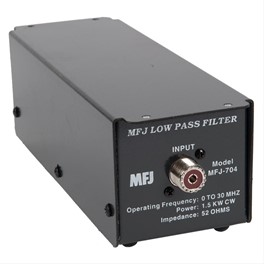
- Low-pass filters—If you are trying to reject FM BC or Public Safety band signals when operating on HF, there are quite a few 100-watt low-pass filters available, like the MFJ-704 below. These will also prevent harmonics from an HF transmitter from interfering with over-the-air reception of TV and FM signals.
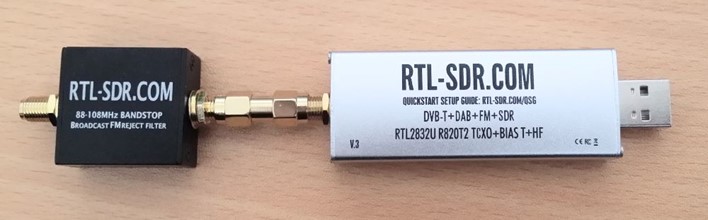
- Band-stop filters—Broader than single-frequency notch filters, band-stop filters are available that cover the entire 88–108 MHz band but are receive-only. FM band-stop filters will work well with the wide-band SDR receivers operating at VHF/UHF/Microwave frequencies.
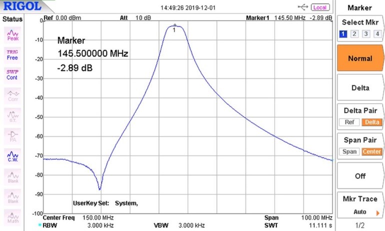
- Band-pass filters—For transmitting-level use, a band-pass filter on one of the VHF or UHF amateur bands will reject both FM BC and Public Safety band signals. The ARRL Handbook features a 2-meter band filter originally published by the RSGB. Several manufacturers offer band-pass filters for the 2 meter and 70 cm bands. The filter response of the SOTAbeams BPFT-100 shows the out-of-band rejection typical of these filters.
In an upcoming blog article, I’ll discuss the related problem of harmonic filters and provide an overview of how to use transmission line “stubs” to do the job—without an L or C in sight!