
It is not unusual to be able to hear the harmonics of a nearby transmitter, amateur radio or not. No signal is a perfect sine wave and it’s easy to overdrive or mistune a transmitter or amplifier, too. Less well known is that even a perfect signal can result in harmonics and other unwanted “spurs” (short for spurious emissions) created entirely by unpowered “passive” components.
These spurs occasionally interfere with other stations but are most noticeable in multi-transmitter stations (such as at Field Day and Multiop stations) or if a single-operator station is transmitting on one band and receiving on another. The “single-op, two-radio” or SO2R station is a good example. Let’s take a look at what these signals are.
Harmonics and Products
Every practical signal has some harmonic content, even those generated by a crystal oscillator. Bandpass filters will reduce the harmonics, but they’ll still be audible in today’s sensitive receivers. The goal is to reduce their amplitude until they don’t affect your operating.
Harmonics are generated whenever ac current flows through a non-linear element of a circuit. The element can be intentional, such as a diode in a frequency multiplier circuit where we are trying to generate harmonics. It might be unintentional, such as a diode created by the junction of two dissimilar metals. Sometimes the element is both!
Mixing products or Intermodulation Distortion (IMD) products are caused when two or more signal currents flow through the non-linear element. (In the figure below, the non-linear element is the diode, D.)
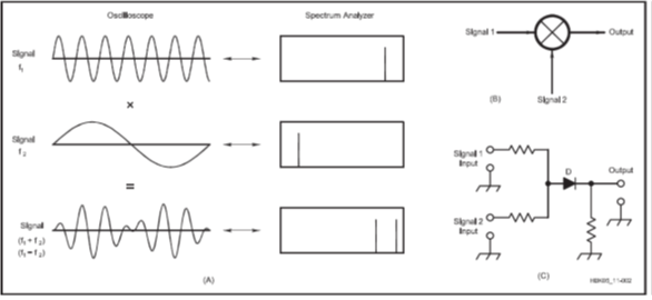
The basics of mixing showing the input and output waveforms and spectra, along with the symbol for a mixer and a schematic showing a circuit typical of a diode that creates mixing products. (Graphic courtesy of the ARRL Handbook from the Receiving chapter.)
This is the same process for mixers in radios where the input RF and LO (local oscillator) signals are combined in diodes to generate new signals at combinations of the sum and difference of the two input signals. If the currents in a circuit or component are so strong that the device is driven beyond its linear range, the result is also many combinations of signals from the intermodulation process.
IMD products are not at the harmonic frequencies of either signal. They are at frequencies equal to the sum and difference of multiples of the input signals. This is expressed mathematically as nf1 ± mf2 where n and m are integer values greater than zero (i.e., 1, 2, 3, etc.). The sum of n and m determines the “order” of the IMD products. Odd-order products are created when the sum of n and m is an odd number, usually 3, 5, 7, or higher values. Even-order products have an even sum of n and m. IMD products can be close to or far from the signals that combine to create them.
Audible Clues
Does it matter whether the interfering signal is a harmonic, a mixing product, or an IMD product? Yes, it does, and for a couple of reasons. The first is identifying the source of the signal. Harmonics produced in a properly operating transmitter chain are generally “clean” and sound like a single tone in the receiver. The higher harmonics may drift somewhat and if the signal is modulated (AM, SSB, FM, etc.) you will hear the modulation although it will be distorted from being multiplied in frequency. These harmonics are generated as part of the transmitted signal, so you basically know the source from the quality of the signal.
IMD products are produced by two or more transmitted signals being present simultaneously. Since most amateur signals are intermittent, an IMD product produced by an amateur signal will be synchronized to the transmissions. This will be a clue—what is transmitting when the interfering signal is present? The modulation of the product (if it is from a voice signal) may also help to identify the source.
Finally, mixing products from RF current picked up by passive components like diodes or junctions in transistors or ICs can have a signature raspy or buzzing sound. This is particularly true when the cause is a poor, loose, or corroded connection (including rust) between conductors. Modulation from the RF signal may also be present on the product signal. The cause can be a loose connection in an antenna, a rusty U-bolt on a mounting bracket, or even oxidized aluminum tubing. The rasp or buzz is caused by the many non-linear paths current can take through the connection.
While this article is not about active devices creating interference, it is worth mentioning that strong RF signals picked up on power leads can affect switching power supply operation. The RF signal can “confuse” the regulation circuits, causing the switching frequency (and the switching products) to change with the transmitted signal. Or the RF signal can upset the voltage reference of the switchmode controller, causing the product frequencies to change along with the transmitted signal. Battery chargers can act similarly. Don’t count these ubiquitous devices out when tracking down interfering signals.
What Generates Interfering Product
There are obviously lots and lots of possible ways to produce these signals. We are fortunate that our transmissions don’t create very many that are strong enough to cause problems! In general, it is important to remember that RF current in a conductor is required. Components like diodes aren’t big enough to pick up enough RF to produce an interfering signal themselves—they need to be connected to something. Amateur stations do have a lot of wires that pick up RF, even if you didn’t intend for or expect them to do so. The same wire can pick up RF, conduct it to the offending device, and then radiate the interfering signal—all without power being applied!
Harmonics and other products are generated any time current flows through a non-linear element, meaning that a graph of current versus voltage is not a straight line. Wires and resistors are linear devices because a doubling of voltage across them also doubles the current through them in either direction. The semiconductor junctions in diodes and transistors and ICs, however, are “square law” devices in their forward conducting direction. That is, the current through them is related to the square of the voltage across them. This creates a curving graph of current versus voltage which is quite non-linear! In the reverse direction, the junction acts like a very small capacitor. This is often over-simplified in a graph showing no current from reverse voltage and a straight vertical line for current from forward voltage. This non-linear relationship between current and voltage is very effective at generating harmonics and mixing products.
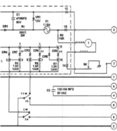
An inspection of equipment in the antenna system will reveal many rectifiers, LEDs, transistors, and ICs either directly connected to a cable or wire or in a part of similarly connected piece of equipment. All of these have square-law components inside. Rotator control boxes and their long multiconductor, unshielded control cables are particularly good examples. Look at the schematic of the control box below and you’ll see several rectifiers and LED indicators. The RF picked up by the control cable is conducted right to the switching and indicator circuits, where it is rectified and passed back to the control cable to be radiated like the incoming signal. (The figure is a partial schematic of the Hy-Gain Tailtwister T2X control box.)
The other common generator of undesired product signals is a corroded connection between metal conductors. The corrosion creates a large number of tiny junctions between the conductors. Everywhere there is a current path through the corrosion, a non-linear junction results, each somewhat different from all the others. This creates an enormous number of low-level products all across the RF spectrum. Rust is a great example and so is oxidation of aluminum and other metals.
Another generator is a junction between different conducting materials, such as galvanizing and copper or between aluminum and stainless steel. These create a type of Schottky barrier diode with the usual non-linearities. As you might imagine, there can be a lot of these around your station.
Finally, we have the original signal generator—a spark! Herr Professor Hertz used sparks to convert dc voltage to electromagnetic waves in the late 1880s. The first wireless transmitters were giant spark-producing machines so dangerous they were often banished to their own building. (That’s where the term “radio shack” comes from, by the way.) A loose connection in an antenna, weeds against an electric fence, brushes in a motor—all produce RF energy as wide-spectrum noise.
Finding Sources
To keep this from becoming an entire chapter of a book, let’s focus on the sources that might be within or near your station or in the antenna system. Further, let’s assume the signal is not continuous and only present when you’re transmitting. This narrows your search to two likely suspects: a semiconduction junction in a diode or transistor or IC or a poor or corroded connection. Also, the source of the signal is probably close to your station or antenna. (The ARRL Handbook has a more detailed description of how to characterize, find, and fix interference sources in the RFI and EMC chapter of the 2023 edition.)
Now it’s time to hunt for the source or sources. If you have a portable receiver, it is very helpful to listen to the same signal you hear on your regular receiver while moving the receiver around to find out where the signal is strongest. Another option is to use a portable spectrum analyzer or SDR USB dongle-and-laptop. If possible, enlist a friend to do the transmitting while you are busy hunting. Similarly, the friend could watch the signal strength on your in-station receiver as you hunt for the source. There is an excellent series of YouTube videos by Don Kirk, WD8DSB showing how to track down RFI sources, even to a single circuit breaker!
Start by verifying that you can hear or see the noise on the receiving equipment. If it is really strong, reduce receiver gain, reduce the transmit power level, or use a small loop or whip antenna to cut the signal level. A medium-strength signal is better when you’re getting close to the source. (This may sound like a direction-finding exercise because it is!) If you are hunting a wide-band source, you might also be able to use a battery-powered AM receiver tuned high in the band between channels.
Walk around outside the station, noting where the signal is strongest. If you have several feed lines and control cables, “sniff” each one by holding the receiver or its antenna close and noting the signal level. Don’t be too focused on the ham equipment and wiring—anything metallic like fencing, gutters, power lines, siding, etc. could be the culprit.
Once you’ve found a loud spot, if it’s a feed line or control cable, follow it to either end. Do a close visual inspection. Check out antenna feed line connections, splices, baluns, or impedance transformers, etc. On rotators, inspect each connector or terminal strip. Shake or strike the antenna or feed line and listen for changes in the interference. Follow the cable back into the station and disconnect it where convenient to see if the signal goes away. The goal is to trace the cable back to a piece of equipment where the signal is being generated so you can troubleshoot it.
Corroded connections outside can also be found by looking for the “hot spots.” Wiggling or shaking is often a good way to find a poor connection outside because the interference will change or even disappear (for a time). Look for rusty hardware, overlapping sheet metal, loose electrical cords or lights, even metal fencing hardware. Water getting into coax connectors also causes interfering signals. Disconnect the connector and visually inspect it for corrosion or oxidation.
Fixing and Preventing Sources
Once you’ve found a source, the rest will seem easy. It’s the hunting that is the hardest. If you find a corroded connection or something similar, the first step will be to clean it! Remove corrosion with a brush or sandpaper, then try to attach the pieces together more robustly using a corrosion preventative compound, if possible. Corroded connectors should probably be replaced outright.
As an example, a friend discovered poor connections at the junctions of aluminum gutter were creating a raspy harmonic on his 40 meter signal. Cleaning the contact areas helped, but a couple of sheet metal screws through the junction cleared up the noise almost all the way. He found the source by listening with a portable AM receiver while wiggling the gutter sections where the interference was loudest.
You can be proactive about RFI generators outside by watching for developing rust and corrosion. When you assemble, install, or build with metal parts, take extra steps to make sure the parts are securely connected to each other. Use corrosion preventative compounds like Noalox or Penetrox where appropriate. When you are assembling an antenna, take extra care to be sure all connections are protected from oxidation and use stainless steel mounting hardware to prevent rust from developing. Use an anti-oxidation compound between all aluminum parts to prevent oxide from forming and keep the surface-to-surface connections clean.
Inside the station, start with a good equipment bonding scheme so that all equipment is at nearly the same RF voltage. This reduces the amount of interference-causing current flowing between pieces of equipment. Be sure to use shielded cables with good connections to bonded equipment enclosures. Use ferrite cores to block common-mode RF current on cables from reaching any sources. For inside equipment that is connected to cables extending outside the station, look for rectifiers, relay kickback diodes, LED indicators, etc. Solder a bypass capacitor (0.01 µF is typical) across each diode as shown in the figure below—it will not affect performance at low frequencies or dc. This “shorts out” the offending junctions at RF. Bypass control inputs and outputs that go directly to an IC or transistor. (Don’t bypass RF inputs and outputs, of course.) Be sure power cables, both ac and dc, are filtered.
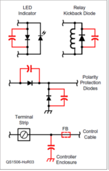
Several common applications of rectifiers where bypassing with a capacitor might prevent interfering signals from being generated. (Graphic courtesy of the ARRL from Hands-On Radio Experiment #149 – Accidental Mixers.)
As an example of how to neutralize in-station sources, I’ve experienced interference from a rotator control cable that picked up a transmitted signal and carried it right to a rotator control box and its internal rectifiers. The box was plastic, so it offered no shielding against the common-mode RF and bypassing the cable conductors to the metal chassis only helped a little. What did the trick was placing a bypass capacitor across each rectifier and LED in the box.
Summarizing Sources
At this point, you may be thinking that sources of harmonics and unwanted spurious products are all around us. In truth, they are, but most don’t generate enough energy to be objectionable. Now that you know how the “junk” is generated, though, you can keep watch in and around your station to avoid creating or installing sources inadvertently. When you purchase a new gadget or install a new antenna or structure, you can “junk-proof” it before installation. A maintenance program that includes a survey of outside equipment can also prevent problems before they become an issue on the air, as well. You can only prevent passive sources by being active!