
The Off-Center Fed dipole (OCF)–also called a Windom by many–has received mixed reviews among amateur radio operators. Although thousands of hams use and love these multi-band antennas, some people, including a few well-known antenna experts, view the OCF as a common mode current (CMC) generator or even an outdoor dummy load. But if built properly, the OCF is a great multi-band antenna that is ideal for hams who have limited space.
A ham friend of mine calls it an OCD antenna, poking fun at the lengths to which some hams will go to find the perfect feedpoint. In reality, it is one of the simplest and most economical antennas, and its length is comparable to a conventional dipole. This multi-band antenna doesn’t require traps, loading coils, or a tuner on its operational bands.
History
It was Loren Windom and several others at Ohio State University who discovered how changing the feedpoint would affect the coverage and performance of an antenna. The original Windom antenna from the late 1920s was an off-center fed resonant dipole with a single wire feedline of any length. It was intended to be used on one frequency only. Its main advantage was that it could easily be matched to a tube transmitter. Today’s versions, based on the original Windom, include the common OCF and Carolina Windom.
How it Works
Like most HF antennas, the OCF is based on the dipole. By measuring impedance between the center and the ends of the dipole, you may find impedances between 73 and 3,000 ohms. For the OCF, the goal is to determine a point where the impedance is low enough to be useable on multiple bands. You can accomplish this with a feedpoint placed somewhere between 45 and 20 percent of the total length from one end of the antenna.
Many OCF antennas are constructed according to a standard formula which places the feedpoint one-third of the way from one end, making two elements: one 33% and the other 67% of the total length. This results in low SWR on the lowest fundamental frequency for which the antenna is cut, and also on the even harmonics of that fundamental frequency–unlike a dipole which favors odd harmonics.
The OCF dipole presents a reasonably good match to the transmitter across multiple bands, which are even harmonics of the fundamental frequency, including 80, 40, 20, 12, 10 and 6 meter bands. Feeding the OCF dipole at a point that is one-third of its length from one end typically yields a higher feedpoint impedance, approximately 200-300 ohms, as compared to the center-fed half wave dipole at 73 ohms. Most OCF antennas use a 4:1 impedance transformer at the feedpoint to match 50 ohm coax.
It seems that many OCF builders have found their own “sweet spot” through experimentation. For example, some hams have reported choosing a 20%-80% split in conjunction with a 4:1 current balun, providing a usable antenna on 80, 40, 30, 20, 15, 12, and 10 meters, with SWR readings less than 2:1 on these bands.
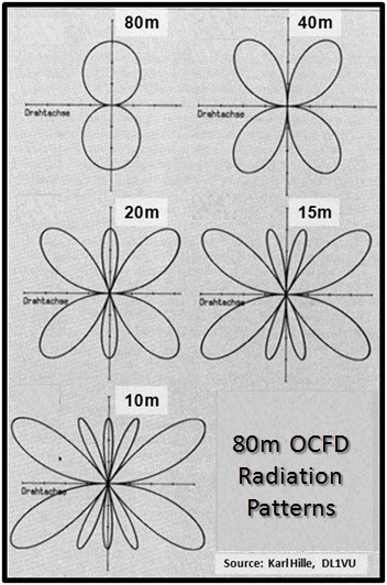
OCF antennas begin with a radiation pattern similar to a conventional dipole at its fundamental frequency, but differ on the harmonic bands. In the illustration below, you can see that the figure 8 pattern splits into multiple lobes on the higher bands. In real life, however, the nulls are not as deep as the picture implies.
Installing the OCF
There are tricks to improving the performance and band coverage on an OCF once you’ve settled on the location of your feedpoint.
Distance above ground affects impedance–the higher the feedpoint, the higher the impedance. Typically, most instructions suggest the feedpoint be at 30 or more feet above ground level. Several sources suggest switching to a 6:1 balun if the antenna height is 70 feet or more.
Keep the OCF antenna clear of surrounding objects as much as possible, especially metal. They can be installed as a flat-top or inverted-V. The inverted-V should have an inside angle of no less than 120 degrees between the elements, and each element end needs to be at least 8-10 feet above ground. Whenever possible, run your coax an equal distance away from both legs of the OCF antenna as far as possible–don’t run it parallel to the antenna.
Adding a vertical component can enhance performance by lowering the angle of radiation. The Carolina Windom is a variation of the OCF with a choke balun (line isolator) placed 22 feet below the 4:1 balun on an 80-10m off-center fed antenna. This allows the 22 foot vertical section of feedline to act as a radiator. The radiation pattern when using this vertical radiator combines both horizontal and vertical radiation components and lowers the effective angle of radiation, getting more of your signal near the horizon.
Performance
Essentially, an OCF dipole is just a dipole which is not fed at its center; it performs much like a center-fed dipole. It provides multi-band operation on even harmonics, often without using a tuner/matchbox. Overall antenna system losses are lower because lower SWR on the OCF’s operating frequencies means less feedline loss and lower losses from using a tuner/matchbox, while presenting a good match to the transmitter.
OCF Antenna Advantages
- A single antenna will cover almost all HF bands
- Lowest cost per band compared to any good multi-band antenna
- Low radiation angle with good efficiency
- SWR generally well under 3:1 on most bands, except for 80/75m where a tuner is helpful. (This is typical of all 80m dipoles)
- No need for a separate matchbox. The transceiver’s built-in ATU will usually work to minimize SWR
Disadvantages
- The SWR is not the same on all bands; it varies on each band
- Resonant frequency is not independently adjustable by band
- The off-center feeding results in an increase of common mode current trying to flow down the outer shield of the coax. With proper choking, this can be held in check, at least for moderate power levels up to 1kW
- The OCF has somewhat more pronounced nulls in its radiation pattern than
- a doublet on its harmonic frequencies