
Some of the biggest challenges presented to the Little Pistol, especially one who wants to become a Medium Gun, are the low bands. This generally means 10 MHz and lower, but for contesting that starts with the 7 MHz band. Assuming budget and space are limited, what’s a ham to do? In this article, I’ll talk about some simple antennas that work year-in and year-out. But first, some basics.
TANSTAAFL
There ain’t no such thing as a free lunch, especially on the low bands, although some lunches are cheaper than others. It is important to remember what creates a radio wave: acceleration of electrons over a distance. This is the origin of “Put some fire in the wire!” Generally speaking, the higher the current and the straighter the current path, the more power is radiated as an electromagnetic wave (i.e., a radio wave). This is why a half-wave dipole, radio’s oldest antenna, works so well.
Folding, coiling, bending, loading—all of these things reduce efficiency at radiating a signal. I can hear some antenna designers out there saying, “Wait a minute…” and yes, there are exceptions. But for ordinary antennas, here’s a good rule of thumb: Put up wire in as much of a straight line as you can at an appropriate height, and put current into it. Things may get complicated if you are using the antenna on multiple bands or have very limited space, but strive to satisfy this general rule and you can’t go wrong.
Height Above Ground and Ground Loss
Okay, so you have a nice straight wire; what’s all this about “appropriate height”? Some of the signal from a horizontally polarized antenna (one with the radiating elements parallel to the ground) reflects from the ground and combines with the rest of the radiated signal. In some directions, these signals add together and in other directions they subtract. You can control the adding and subtracting by varying the distance between the antenna and the reflecting surface (i.e., height above ground).
The figure below (from the ARRL Antenna Book’s 24th edition) shows several examples using a dipole. In free space, the radiation pattern of the dipole, seen from the end of the wire, is circular. It radiates equally in all directions. Let’s put conductive ground under the dipole. When the dipole is very low, the adding direction is straight up. This is great for NVIS (Near-Vertical Incidence Skywave) and regional coverage. It is not great at all for DX since little signal is being radiated at low angles for the necessary long skips off the ionosphere.
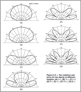
As the dipole moves higher, the adding direction starts to come down until at one-half wavelength (λ/2), the subtracting direction (a null) is straight up, and the adding direction (a lobe) is just a bit under 30 degrees. This is much better for DX. Raising the dipole to 3/4λ lowers the adding direction and creates another straight up. The process continues with more adding directions created as height increases. For Little Pistols, λ/2 is a good height to shoot for at 40 meters (66 feet or so, it’s not critical). On 80 and 160 meters, get the antenna as high and as straight as you can.
Now let’s talk about ground loss. For vertically polarized antennas, you can waste some of your signal heating up the ground. If there is a high-current (low impedance) point at ground level, such as for a λ/4 ground-mounted vertical, then there will be high current in the ground around the antenna. Dirt is generally not a very good conductor (although salt marshes aren’t bad), so current flowing through it will generate heat just like it would for any resistance. Heat doesn’t get you through many pileups!
To minimize this ground loss you can move a high-current feed point away from the ground (raise the antenna), change to a low-current high-impedance feed point near the ground (lots of end-fed half-wave antennas are used this way), or change the ground conductivity. The first two tactics to keep high current from flowing in the ground have their own challenges. Raising the antenna can be difficult for full-size low-band verticals. A low-current, high-impedance feed point creates issues with high voltage and needs an impedance transformer for the feed line. Reducing the ground resistance itself is another tactic.
Wires laid out radially from the antenna feed point (called radials, surprisingly) on the ground or very close to the surface give the current that would have to otherwise flow in the ground a low-resistance path back to the feed point. Current will avoid dirt if a wire is available! More wires (to a point) reduce the losses. Wire mesh (like chicken wire) also works. The wires do not have to be any particular length (they’re not resonant or tuned when on the ground). Just use as many of them as you can, close together near the feed point where lots of current is flowing. They can be bent and don’t have to all be the same length. Reducing ground loss contributes directly to your radiated signal at any angle.
Half-Wave Dipoles and Inverted Vees
I have mentioned the dipole already. A λ/2 long piece of wire, fed in the middle with coax, about λ/2 above the ground is probably the best bargain in ham radio. Although the books show a deep null off the ends of a flat dipole, in practice there is some signal radiated in those directions due to reflections and coupling to the feed line. The dipole can be used on its odd harmonics. If fed with low-loss open-wire or window line, it can also be used on the even harmonics where feed point impedance is high.
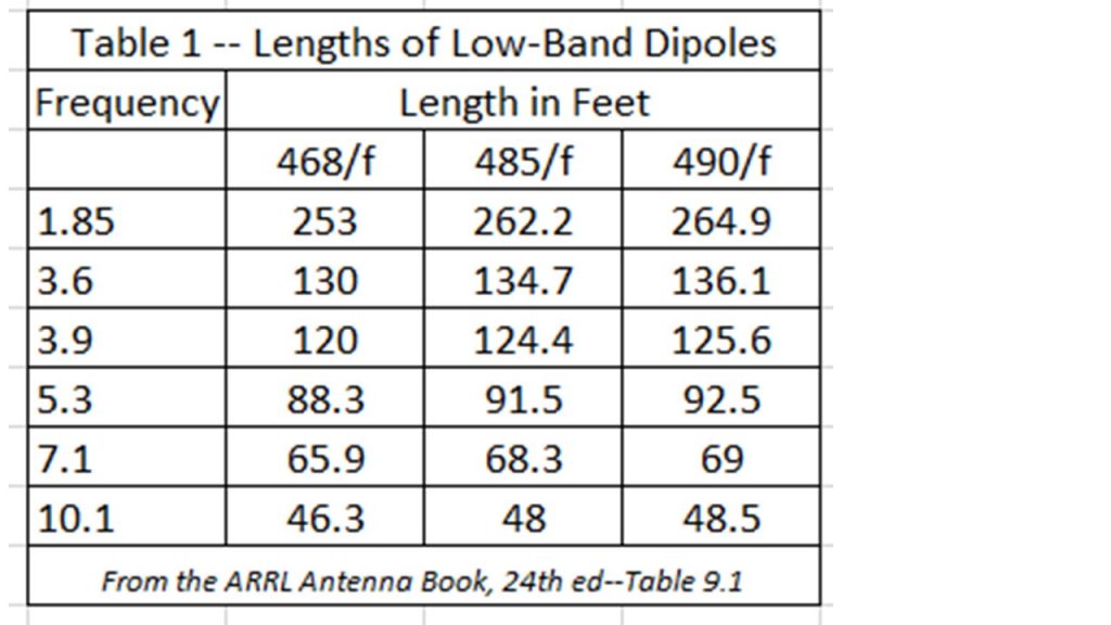
Make learning how to build, install, and tune dipoles one of your first projects. You will not regret it. Start with the antenna somewhat long (I use the formula: length in feet = 485/frequency in MHz) and practice adjusting the length in a single step to get to the desired resonant frequency.
If you don’t have enough room for a full-length dipole, you can let the ends hang down or bend them to the side. That will reduce radiating efficiency a little bit but having the rest of the dipole up in the air will make up for the small reduction in signal. If you only have one central support like a tree or mast, get the feed point as high as possible. That’s where current is highest in the antenna and you want it high above the ground. Slope each leg (side) of the dipole down toward the ground and you’ve made an Inverted Vee antenna. The slope doesn’t have to be symmetric. One leg can be flat and the other sloped, for example.
Does a dipole or Inverted Vee need a balun? It’s not a necessity. The feed line shield’s outer surface will probably carry some of the antenna current, but that will radiate, too. The more symmetric the feed line with respect to the dipole’s legs, the less current will flow on the feed line, as a rule. To block the current from flowing on the feed line, which can result in RF current in the station, a choke balun can be used at the feed point. A simple coil of coax will help, but if you really want to do the job right, use a ferrite core or either build your own or buy one.
Quarter-wave Verticals and Inverted Ls
Another basic and very popular low-band antenna is the quarter-wave vertical. Ground-mounted, it has a low, easy-to-match feed point impedance (35 ohms or more) and generally doesn’t require a lot of mechanical support. On 40 meters, the vertical will be 33 feet (or so) long, and that’s manageable with aluminum tubing or a multi-section fiberglass pole holding up a wire. On lower bands, the length makes them harder to build and support. On 80 meters the vertical will be 66 feet, and on 160 meters around 125 to 130 feet. Wire verticals hung from a tall tree make a good antenna.
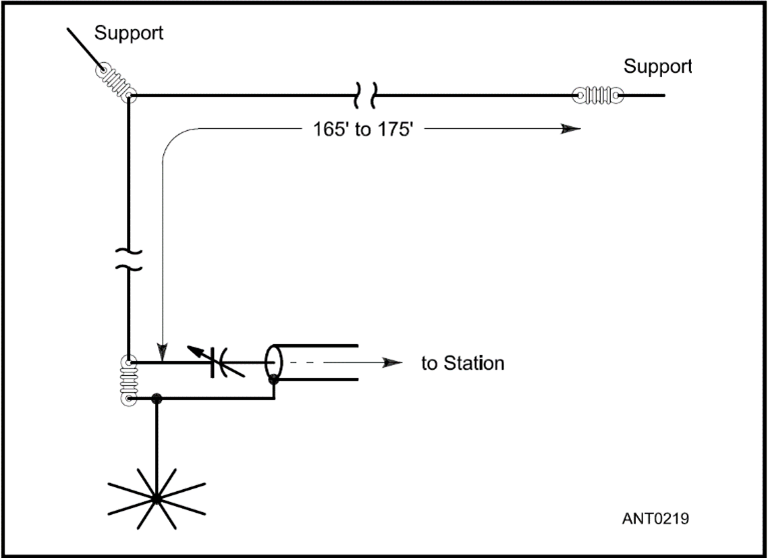
Like the dipole, the antenna doesn’t have to be totally straight. A popular variation for 80 and 160 meters is the Inverted L. (The figure below from the ARRL Antenna Book shows a 160 meter design.) This is basically a wire vertical bent at a right angle. Make the vertical part, where the highest current is, as long as possible and stretch out the bent-over part horizontally. Typical Inverted L designs are about 5/16λ long. Why? As the antenna length increases, so does the feed point impedance. Near 5/16λ, the impedance is approximately 50 ohms of resistance with some inductive reactance. Feeding the antenna through a series capacitor (100 to 800 pF for 160 meters) cancels out the inductive reactance, resulting in a great match to coaxial cable.
Another common compromise is to add inductive loading to a vertical antenna to lengthen it electrically and still have a manageable height. Multi-band verticals are sold by several manufacturers, such as the Butternut HF2V for 80 and 40 meters. Some manufacturers add capacitance with spokes or “hats” high on the antenna to lengthen them electrically. Coils and capacitance do make the antenna structure resonant and adjust feed point impedance for a good match, but they don’t radiate much signal. The more “gadgets” on an antenna, the less radiating element it has. For low-band operation, get the longest (tallest) one you can since that will usually have the most radiating element.
Verticals are omnidirectional antennas, even if sloping a bit. See the cautions in the previous section about ground losses, though. Spend some time and effort installing radials or a ground screen and you won’t regret it.
Slopers and End-Fed Half-Waves (EFHW)
If you already have a metal tower or mast, consider a sloping dipole. They may have a bit of directivity in the direction away from the metal support but are nearly omnidirectional. Some designs combine several dipoles with a coax switch to act as a switched-direction array, although this takes some tuning and adjustment to optimize. At smaller stations, this is a good option using 40 meter dipoles.
The half-sloper, often used on 80 and 160 meters, consists of a λ/4 wire attached to the top of a tower or metal mast and fed with coax at the junction. Some designs connect the shield to the wire and others to the metal support. The length of the wire and the angle from the tower both affect tuning. Experimentation is the name of the game.
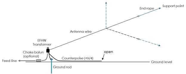
The EFHW shown below has become a very popular antenna that works well if the feed point impedance-matching transformer is well-designed. With one end near the ground and the other supported by a tree or mast, it is a sloping half-wave dipole on its fundamental frequency. It can also be used on harmonics with a radiation pattern that has numerous lobes and nulls. One useful bonus of the EFHW is that by connecting the coaxial feed line directly between the antenna (bypassing the transformer) and a ground screen of radials or mesh, the EFHW becomes a sloping λ/4 vertical. Thus, an 80-10 EFHW can also be used on 160 meters with fairly good results!
Vertical Loops
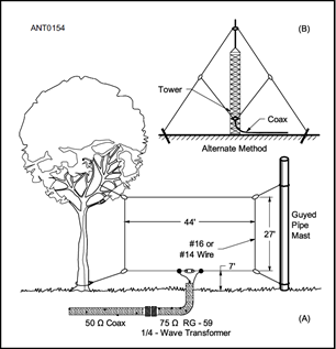
The vertical loop is another easy-to-build, inexpensive low-band antenna. The delta loop shown in the figure below is the most popular, only requiring one support. It’s one full wavelength in circumference on the fundamental (lowest) frequency, so it can also be used on harmonics. For NVIS and regional coverage on the lowest band, feed it at the bottom either at a corner or in the middle of one side. To lower the angle of radiation, move the feed point and high-current point to the top of the antenna. The loop can have any open shape—triangle, square, rectangle—and will perform reasonably well with a feed point impedance of about 100-120 ohms. This will require an antenna tuner if you want to use the loop on multiple bands. A single-band loop can be matched with a λ/4 synchronous transmission line transformer (also known as a Q-section or a λ/4 matching transformer). On its lowest band, the loop will perform about as well as an Inverted V with a feed point at the same height.
Horizontal Loops
Another popular antenna for low-band operating is the horizontal loop, as shown below from the ARRL Antenna Book’s chapter on Multiband HF Antennas. It’s often easier to get a full wavelength (or more) of wire in the air as a horizontal loop than vertical. Rarely are these big loops more than λ/2 above ground, particularly on 80 and 160 meters, so they tend to be “cloud burners” that are good for regional coverage. On higher bands, the angle of radiation comes down but the radiation pattern has a lot of lobes and nulls. Feeding a big horizontal loop with open-wire line and an antenna tuner makes for a good all-band antenna with the occasional DX surprise.
Extended Double-Zepps (EDZ)
Having been rediscovered in recent years, the EDZ is inexpensive and has a few dB of gain on its primary band, usually 20 or 40 meters. The EDZ is two 5/8λ elements connected end-to-end with a tuned section of open-wire line in the middle. On the design band, the open-wire line presents approximately 50 ohms where it can be connected to coax using a choke balun. A 40 meter EDZ is a bit longer than an 80 meter dipole (around 166 feet) and can be used on higher bands through a tuner and on lower bands by shorting the coax conductors together and driving the antenna against a ground screen. West Mountain Radio provides a handy calculator for EDZ design here.
Practice Makes the Master
When you are moving up the ranks of DXing; contesting; or hunting parks, summits, or islands, it’s important to make the most of what you have. Keep improving your antenna farm, taking stock of what works and doesn’t work for your station. Study antenna books and articles to see why designs work and whether they might be a candidate for your station. Here are some to have in your library:
ARRL Antenna Book and Antenna Classics series
ON4UN’s Low-Band DXing (out of print but often available used)
RSGB’s series of books on HF Antennas
On the air, keep track of what works and what doesn’t. Ask other station owners what they are using and share notes. Find out when and where your antennas are most effective and use them to the best of your abilities. Many pileups have been cracked with small antennas, low power, and skill. We hope you’ll see your call sign in the top scores soon!