
Here we are, just past the solar minimum with Cycle 25 just getting started. Fall is a great time for HF propagation as we’ve discussed earlier. Should you focus on those welcome-but-unfamiliar high band openings on 15, 12, and 10 meters? Those will be a lot of fun, but for DXing and contesting—any form of radiosport, really—the low bands are still in great shape.
There will be lots of activity on 30, 40, 60, 80, and 160 meters through the fall and winter. Why not take some time to improve or upgrade your low-band antennas? This column will focus on how to get more out of a low-band vertical, a very popular antenna for these bands.
Popular Low-band Vertical Styles
Because wavelengths get longer and longer as you go lower and lower in frequency, beams and multi-element arrays start to become unwieldy. Sure, it would be nice to have a 2-element Yagi for 80 meters, but most stations aren’t equipped with such a beast. It’s a pretty good bet that most medium and small stations are equipped with a ground-mounted vertical antenna, usually a multi-band design.
The quarter-wave ground plane antenna is the basic model for single- and multi-band verticals. These are pretty easy to make, even for 80 meters if you have a suitable tree available. If you have a horizontal dipole for the lowbands, consider a single-band vertical to add some low-angle punch. The oft-quoted formula for length in feet is 234/f in MHz, but you’ll find that to be a bit too long if you use tubing—be sure your antenna length can be adjusted. A wire vertical will be resonant closer to the formula’s value but be ready to trim the antenna. Without loading or traps, these are wide-band antennas and will cover the entire band except maybe 80 meters.
A trap or trapped vertical such as the classic Hustler 6BTV can operate on multiple bands by using coils and capacitance to control the electrical length of the vertical, making it look like a ¼-wave design. The coils in the traps act as loading coils below the resonant frequency of the trap, so these designs cover a narrower segment of the bands.
Half-wave and similar designs try to behave like a half-wave dipole standing on one end. They are fed at one end where the impedance is quite high. (The End-Fed Half-Wave is this kind of antenna.) They typically have an impedance transformer at the bottom of the vertical where the feed line is attached.
The 43-foot vertical straddles the quarter- and half-wave worlds by not attempting to be resonant on any band, relying on an impedance matching unit at its base. It’s similar to one of the various non-resonant doublet wire antennas…but standing on one end.
If you have a tree or two and can hang some supporting rope, you can put up an Inverted L. This is similar to a regular ¼-wave vertical but bent to have a good fraction of its length parallel to the ground. The top horizontal section is extended so the antenna is longer than ¼-wave. This is done to raise the resistive part of the feed point impedance from 35 ohms or so, typical of a ¼-wave vertical, to 50 ohms. There is some additional inductive reactance because of the extra length, but that is canceled with a series capacitor to give a 1:1 impedance match.
Finally, if you do have a horizontal dipole in the back yard, consider turning it into a top-loaded vertical. Short the feed line center conductor and shield together where the cable enters your station and connect them to the center conductor of the coax going to the transmitter. Connect the shield of the transmitter coax to a ground system. You have just created a flat-top T antenna with the dipole acting as top-loading and the shield of the feed line acting as the vertical element.
There are many variations on the ¼-wave ground plane. The ARRL Antenna Book offers numerous designs, tables for different bands, radiation patterns, information on ground planes, and a lot more.
Straighten out the current
So what is the difference between all of these designs? Isn’t a ¼-wave a ¼-wave? Not really—for antennas, it matters whether the antenna’s radiating surfaces are straight, coiled, folded, or otherwise squashed in order to reduce size. That’s because the most effective way to get an electron to radiate energy is to accelerate it back and forth in a straight line, such as in a dipole.
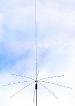
By applying voltage to the antenna feed point, the electrons are made to move back and forth. If the path is straight, the familiar radiation patterns for dipoles appear. If some of the antenna is coiled up, the electrons still accelerate back and forth but in a small circle and much less energy is radiated. This is the same situation for antennas that are folded (linear loading) or, like the CushCraft MA160V below, have capacity hats that add capacitance along the antenna. These antennas may all have a 50-ohm feed point impedance, but the straighter they are, the more efficiently they will radiate and the wider their operating bandwidth will be.
Here are some guidelines for you when choosing or designing a vertical antenna:
- Make the radiating, high-current part of the antenna as long and straight as you can. It’s okay to bend that part but no more than a right angle.
- Pick antenna designs or models with the longest radiating sections, especially if traps or coils or hats are used.
- Use the least amount of inductance in a loading coil needed to resonate the antenna.
- Center loading is the most efficient place for a loading coil. Base loading is the next best choice.
- Top loading with a capacity hat is efficient but can make the antenna mechanically unwieldy.
Cut your Losses
Ground-mounted verticals need to minimize losses from RF energy moving through soil. Horizontally polarized antennas don’t have this problem to nearly the same degree. The best solution is to use a ground screen or ground plane of wires or mesh connected to the feed point at the base of the antenna. Even half-wave designs that don’t require a ground plane benefit from placing a screen below the antenna so that the radiated RF doesn’t have to flow through the soil.
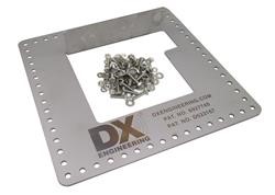
The most common type of ground screen is multiple wires, either bare or insulated, attached to the feed point and stretched out radially away from the antenna, thus the term radials. Use as many wires as you have room for. If you can lay out the wires so they are separated at the ends of the wire by about 1/20th of a wavelength, you have a very effective ground screen. (That separation results in the wires being about ¼-wavelength long, but they are not resonant.) You can lay the radials on the ground or bury them (just an inch or so). They don’t have to be symmetrical and you can bend them or shorten them to avoid obstacles. The important thing is to give the RF another path besides soil. DX Engineering sells radial kits and a handy radial attachment plate.
What if you can’t put out that many radials? Perhaps this is a temporary installation or you simply don’t have that much wire—for a 160 meter vertical that would be a lot of wire. Fortunately, Al Christman, K3LC, did a lot of number crunching and determined the optimum number and length of radials for 40, 80, and 160 meter vertical antennas. Al based the calculations on “how much wire do you have?” so you can tell how to make the best use of the resources at hand. This is all laid out, so to speak, in Al’s National Contest Journal article available here on the NCJ website. The ARRL Antenna Book also has an extensive discussion of radial systems in the chapter, “Effects of Ground.”
You can help yourself out even more by adding metal where the RF fields will be the strongest—right around the base of the antenna. Extra “short” radials between the full-length wires certainly help. Rolls of chicken wire or hardware cloth are also very good temporary additions, such as during a DXpedition or contest. Use jumper wires and split-nut clamp connectors to connect the mesh wire to the feed point. (These meshes are galvanized but will quickly rust if left in place, so they are best for temporary use.) Just remember that the goal is to have as little RF current flowing through the soil as possible.
If you put a coil in the antenna, use large wire (even for QRP—why waste those precious watts?) or refrigeration tubing for high power. Wind the coil with turns spaced about one wire diameter. Large wire and turn spacing help reduce losses from high currents in the coil. If the coil is part of a trap, use a transmitting-type capacitor with heavy plates and rotating connectors. A well-designed trap is not particularly lossy.
Finally, make sure you get the RF to the antenna with a minimum of losses on the way. Use good-quality feed line, even at low power levels. If the coax is buried, be sure it is rated for direct burial or put it in a conduit. Burying the feed line also reduces RF common-mode current flowing on the shield from received noise and from picking up the transmitted signal.
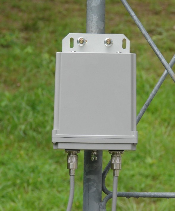
For single-band antennas, build a matching network and put it in a weatherproof box at the feed point. If the feed point SWR will be more than 3:1, put an antenna tuner AT the antenna, NOT in the station, if possible. One of the many remote tuners, like this LDG RT-100, is perfectly suited for this application. The goal is to keep SWR in the feed line low, even at HF, to avoid unnecessary losses.
It’s a Wrap
Summarizing, there are three basic guidelines to spiffing up your low-band vertical:
- Straighten it out so the RF current flows in a straight line
- Install the best ground screen you can from the wire you have, supplemented with mesh for temporary boosts
- Minimize losses by using heavy-duty coils, good feed line, and placing antenna tuners as close to the antenna as possible