
If you have ever stood at the base of a tower, looking forlornly upward, wondering “What’s WRONG with that [adjective] rotator?!” you are not alone. That simple piece of gear is so important for an effective antenna system—all the gain and front-to-back in the world doesn’t help if it’s not pointed in the right direction! Now what?
Just saying “it’s broken” is not going to get the job done. You have to decide what type of problem you’re dealing with. Fixing a problem is usually pretty straightforward but only if you know what the problem actually is.
Tip: It’s a ROTATOR, not a ROTOR. A rotator is a piece of equipment that makes something else rotate. A rotor is the thing that rotates. Thanks…I feel better now!
What’s Wrong with It?
It’s so easy to jump to conclusions, especially with a typical ham antenna system that has lots and lots of parts. A misdiagnosis can leave you chasing dead ends for hours or days! So, first, take a few deep breaths and a step back or two.
This article assumes you have one of the most common family of rotators—a Hy-Gain HAM-IV or Tailtwister T-2X with an analog position indication meter in the control box. These rotators have been in production for decades and give reliable service if not overloaded. The manual will also have troubleshooting information, some of which is repeated here. If you have a different type of rotator, you may not be able to repeat these steps exactly, but the general process will still have value.
Start with a visual test. Use binoculars (or a drone!) to look at the rotator from all sides. While a friend or family member operates the rotator, assuming it’s turning, look closely at the rotator housing. Is it moving on the rotator shelf? Sometimes one or more mounting bolts can loosen up (or fall out completely), allowing the rotator to move instead of the antenna system. Can you see that all of the rotator mast clamp nuts are not loose along the U-bolt threads? Look for feed lines that have been caught in the tower or wrapped around it, preventing the rotator from turning. Does the rotator shelf itself appear to be securely mounted in the tower? These can all create problems.
Use your ears by standing at the tower and having your helper release, then reengage the brake wedge. Repeat this several times. You should hear the solenoid activate and produce a healthy “chunk” as the brake wedge is retracted from the rotator housing. If that’s working, have them attempt to turn the rotator in either direction while you listen more carefully for the noise of the motor turning the gears inside. If the rotator brake releases and the motor “hums” but doesn’t turn, the rotator is being prevented from turning by something mechanical.
If any of these problems are present, you’ll have to climb up there and see what the problem is.
Tip: The Tailtwister is well-known for its brake wedge sticking in place. Try turning the rotator in the opposite direction a little bit to free the wedge, then trying to rotate in the desired direction. If the wedge has been stuck for a while, you may have to repeat this step several times to free it.
Electrical Checks
Find your manual or download it. Locate the Troubleshooting section and the schematic, both toward the back of the manual. The need to climb a tower to test a rotator might be avoided with some ground-level checks.
At the Control Box
Let’s start with the control box and make sure it’s at least trying to work. The control box should:
- Turn on (meter backlight comes on)
- Calibrate the indicator circuit to show the antenna’s current direction
If it won’t turn on, you need to check the back-panel fuse and the ac supply voltage. You may have to open the control box to verify that you have ac power where it’s supposed to go.
You’ve used your ears—now use your nose. Does the control box “smell funny” from something burnt or overheating? An extra-warm spot on the top of the enclosure (not over the meter light) can also be a sign of trouble. If either symptom is present, check out the control box transformers (there are two) and the electronic components in the calibration circuit.
Tip: There are LED replacements for the incandescent backlight bulbs which are becoming really hard to find at a reasonable price. This would be a good time to swap.
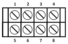
Next, take a good look at the back panel of the control box and the control cable connections. The terminal numbers are shown below. Inspect the wiring carefully. Have any strands of wire gotten loose and shorted to an adjacent screw? If you use crimp terminals on the wires, give them a little tug and be sure the wires are secure in the terminal and not loose.
If the calibration circuit doesn’t work at all, turn on the control box and measure the dc voltage from terminal 3 to 7. It should be around 13 V. If not, disconnect the wires to terminals 3 and 7 (label the wires or note their color), then remeasure. If the voltage is not 13 V, you’ll have to troubleshoot the calibration circuit in the rotator.
Brake Solenoid and Motor Voltage Check
Having determined the indicator circuit is working (or you have repaired it), now check the voltages at all of the terminals. Disconnect all of the rotator control cable wires, making a note of the color for each wire. Here is the usual color code for each circuit:
| Hy-Gain Rotator Standard Color Code | ||
| Terminal | Color | Circuit |
| 1 | Black (heavy wire) | Control box common |
| 2 | White (heavy wire) | Brake solenoid |
| 3 | Green | Indicator circuit supply voltage |
| 4 | Blue | Limit switch (right) |
| 5 | Orange | Motor winding 1 |
| 6 | Yellow | Limit switch (left) |
| 7 | Brown | Indicator circuit return |
| 8 | Red | Motor winding 2 |
Tip: Recording voltages for a working control box and the color codes of the control cable for future reference is a great reason to have a station notebook!
You might have used other colors, but these are recommended in the manual and most stations seem to follow this color code. It’s important that the brake solenoid circuit has heavy enough wire to handle the current. See the manual for minimum wire size on long runs.
Terminal 1 is the common voltage for the whole control box, so connect the negative lead of your multimeter (set to measure ac voltage) to it. On the terminal strip, you should see the following voltages:
- Terminal 2: Approximately 30 VAC when the brake release switch is pressed
- Terminal 3 and 7: See the preceding section.
- Terminal 5: Approximately 30 VAC when BOTH the brake release AND the clockwise (CW) switch are pressed.
- Terminal 6: Approximately 30 VAC when BOTH the brake release AND the counter-clockwise (CCW) switch are pressed.
Any significant differences (more than a few volts) in these voltages indicate an internal transformer or switch problem. If you have a brake-release delay circuit in the control box (it keeps the brake disengaged for five seconds after the motor is turned off so the antennas can coast to a stop before reengaging the brake), it might not be working or have a stuck or open relay. Fix those first.
Resistance Checks
With your control cable disconnected, now is the time to do some resistance checks through the cable and the rotator on the tower. Except for the direction indicator pot, the motor and solenoid resistances are quite low: 5Ω or less. Start by calibrating your multimeter to accurately measure these low resistances. Many meters have a ZERO or CAL function to subtract the value of test lead resistance from a measurement. If you don’t have that function, short the test leads and record that resistance to subtract it from your measurements.
Switch your meter to a low-resistance scale (100Ω full-scale is a typical low range). With all wires disconnected, make each of the measurements in the following table, using the list of color codes you recorded earlier.
| Resistance Checks | ||
| Read Between Terminals | Circuit | Resistance |
| 1-2 | Brake solenoid | 0.75Ω+ cable or leads |
| 1-8 | 1/2 Motor winding | 2.5Ω + cable or leads |
| 1-4 | 1/2 Motor winding | 2.5Ω + cable or leads |
| 1-6 | 1/2 Motor + left limit switch | 2.5Ω + cable or leads |
| 1-5 | 1/2 Motor + right limit switch | 2.5Ω + cable or leads |
| 8-4 | Entire motor | 5 W + cable or leads |
| 8-5 | Right limit switch | 0Ω + cable or leads |
| 4-6 | Left limit switch | 0Ω + cable or leads |
| 3-7 | Entire pot element | 500Ω |
| 3-1 | Pot wiper to element end 1 | 0-to-500Ω |
| 7-1 | Pot wiper to element end 2 | 0-to-500Ω |
| Note: readings 3-1 and 7-1 should add to 3-7 reading Note: include test lead resistance if not calibrated out |
Problems with resistance checks usually show up as open or short circuits. Most cable and wiring faults are open circuits. A control cable that’s been cut or damaged may have multiple open and short circuits.
Indicator Problems
Start with the direction indicator pot. You should measure 500Ω between the wires previously connected to terminals 3 and 7. This is the pot element and doesn’t change with direction. Measure between terminals 1 and 3 and then between 1 and 7. The sum of those two measurements should equal the measurement between 3 and 7. If the rotator is all the way to one end of travel, one of those measurements will be a very low number and the other approximately equal to the measurement between 3 and 7.
If the position indication doesn’t move while the rotator is turning, make sure the control box isn’t in calibrate mode. On most control boxes, this control has a push-on/push-off switch to turn the calibrate adjustment on and off. Other control boxes have a separate switch and calibration pot. If the indicator circuit is left in the CAL position, the needle will indicate a direction but won’t change as the rotator turns.
Another common problem is for the indicator to “skip” or “freeze and release.” This is caused by wear of the pot’s wiper contact in the rotator or dirt/corrosion of the element. A lightning strike can also burn the pot element or wiper. Sometimes, repeated motion of the wiper across the “bad spot” can clean the element enough to use.
Tip: You can test the control box indicator circuit without needing to turn the rotator by temporarily replacing the rotator’s indicator pot with a 500-W panel-style pot at the back of the control box. Connect the wiper to terminal 1 (the common voltage point for the control box) and the element of the pot to terminals 3 and 7. As you rotate the substitute pot’s shaft, the position indication should also move.
Limit Switches
The rotator has limit switches built in that open when the rotator is turned all the way in either direction. This removes power from the motor and keeps it from trying to turn farther. The other limit switch remains closed so the rotator can be turned away from the limit. Sometimes the limit switch or switches get stuck open and the rotator won’t turn in one of the directions. This shows up as an open circuit between terminals 8 and 5 (right limit switch) or terminals 4 and 6 (left limit switch). The open circuit also appears between terminals 1 and 5 or 1 and 6.
Luckily, you can bypass the limit switch at the control box, even though the switch is in the rotator on the tower. Jumper the limit switch terminals corresponding to the direction in which the rotator won’t turn. If it won’t turn right or clockwise (north-to-east), those terminals are 8 and 5. You should read an open circuit if that limit switch is stuck open. Jumper across terminals 8 and 5 with a #18 or heavier wire and try operating the rotator. Terminals 4 and 6 correspond to the other limit switch.
Motor Capacitor
The 120-140 µF capacitor in the control box produces a phase shift between the motor windings. When the capacitor gets old or dries out, it can become very lossy. This makes the motor turn very slowly. The only fix required (or possible) is to replace the capacitor. Be sure it is a non-polarized component that is rated as a “motor start” capacitor.
Summary
While this isn’t an exhaustive list of the ways in which rotators can fail, it should give you a pretty good idea of what the problem is. Maybe you will even be able to fix it from the ground. Or (cough, cough) maybe it isn’t even a problem with the rotator at all. It’s happened to all of us! The key is to have a good multimeter, a list of expected measurements, and take a careful step-by-step approach.