
450…where have I heard that number before? Seems familiar…Oh, right…450Ω window line! Yes, that’s the nominal characteristic impedance of the black plastic-coated parallel conductor transmission line like DX Engineering’s DXE-LL450-CTL. This and similar feed lines are widely used at HF for feeding wire antennas of all sorts, especially those with high-impedance feed points, such as a center-fed, multi-band doublet. It has low loss which is very important at high SWR and that means it is a popular feed line.
And what’s with the title of the article? Why wouldn’t 450 be 450? For starters, nominal means the rated or advertised value, but it is not guaranteed. The nominal value of 450Ω comes from a much older product that was actually “open wire” with small plastic spacers; that was truly “ladder line.” Today’s version is more accurately named “window line” in which the line is manufactured with a solid plastic coating the entire length (like 300Ω TV twin-lead) from which openings, or windows, are removed. The result is a feed line which has a characteristic impedance, abbreviated Z0, from 380 to about 410Ω. I’ll use 450Ω in this article, but remember that the actual impedance will be significantly lower.
Transmission Line Effects
Another reason 450 isn’t 450 comes from the way impedance changes along the length of a transmission line. Remember that impedance is just the ratio of voltage to current. When energy is supplied to a transmission line by a source, such as a transmitter or antenna analyzer, the resulting voltage and current vary along the line. That means at any point the ratio of voltage and current also change, creating a different impedance than the line’s Z0. Let’s call this the line impedance. (Characteristic impedance doesn’t change because it’s determined by the physical characteristics of the wires, their spacing, and the insulation properties.)
If the impedance of the load connected to the line is not equal to Z0, then nowhere along the line will the line impedance be equal to Z0. In terms of antenna systems and window line, if the feed point impedance isn’t 450Ω, then your source won’t see 450Ω anywhere along the line, no matter how long or short it is. The line impedance doesn’t magically become 450Ω just because the feed line has a 450Ω Z0.
Well, what does the line impedance become, then? This is the point in the discussion where I could whip out an equation that would make math majors weep, or produce an equally inscrutable Smith chart…but I’ll try to avoid the trauma! Here are a few simple rules:
- Line impedance is only equal to Z0 if the load is equal to Z0.
- Line impedance repeats every ½ wavelength along the line, no matter what Z0 is.
- Line impedance inverts about Z0 every ¼-wavelength along the line.
- SWR in a feed line is constant, ignoring the effects of loss.
These rules can be imagined as the line impedance moving in a circle around a center that represents Z0. This is shown in the figure below. Any impedance can be located somewhere in this circular area. The red dot represents some random load impedance, Z = R + jX. If the load was a short, it would be located at the left (think “west”) and if the load was an open, it would be located at the right (“east”). If the load was equal to Z0, it would be located right at the center.
The length of the feed line is shown as movement in a circle. Starting at the dot representing the load and moving toward the source, Z moves ¼ of the way counter-clockwise around the dashed-line circle every 1/8λ. (Remember that Ɩ is the electrical wavelength that takes into account the velocity factor of the feed line.) Moving a full ½λ is one full trip around the circle. Moving farther just repeats this process, so moving 1λ is the same as moving ½λ. Moving ¼λ moves the point representing Z to the point exactly opposite where it began—this is called impedance inversion.
Wherever the load impedance dot is actually located, its distance from the center is a measure of SWR for the feed line’s Z0. At the center, where the load impedance matches Z0, SWR = 1.0. Everywhere along the outer edge of the circle, SWR = ∞. In between, SWR is some value between 1 and ∞ that depends on the ratio of Z and Z0. The dashed line is a constant SWR circle that has the same diameter everywhere along the line. (Losses make the SWR circle get smaller as line length increases, but I am ignoring losses in this article.)
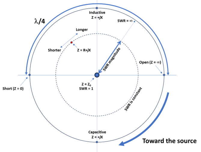
That’s it! You now have a general idea of what happens to line impedance along a feed line connected to the antenna. (You may have also recognized the Smith chart, which has a lot more arcs and circles and scales. A tutorial on the Smith chart is included with the ARRL Antenna Book, or you can read about it online.
Transforming Impedances
If you want to calculate what happens to the load impedance along the line, the simplest way is to use an online transmission line calculator, such as iz2uuf.net/wp/index.php/transmission-lines-calculator/ by IZ2UUF, or download the free spreadsheet-based calculator by AC6LA at ac6la.com/tlmath.html.
Example Line Impedances
To give you an idea of what happens to line impedance in a length of 450Ω window line, here are some examples:
Example #1—A 72Ω 14 MHz center-fed dipole feed point impedance through 100 feet of Wireman 552 (380Ω Z0) window line produces an input line impedance of 97.6 + j120.7Ω. SWR at both the load and input to 50Ω coax is about 5.3:1.
Example #2—Using the dipole of Example #1 on its second harmonic creates a 2400Ω feed point impedance at 28 MHz. The same feed line produces an input line impedance of 197 – j449Ω. SWR at the load is 6.3:1 and at the input to coax 24.6!
Example #3—A 300-Ω 7 MHz folded dipole through the same feed line produces an input impedance of 465 – j40 Ω. SWR at the load is only 1.3:1 but at the coax end of the line, it’s 9.4:1.
None of these are particularly unusual installations and none of them show an impedance of anything close to 450Ω at the input to the line.
What Good Is a 9:1 Transformer?
So, if the antenna feed point impedance is unlikely to be 450Ω, and it is unlikely for the line impedance to also be 450Ω, why would a 9:1 impedance transformer be expected to produce an impedance of 50Ω? We could do a lot of math to find out, but the short answer is, “It won’t.” This answers the question of why connecting window line to a 9:1 transformer often does not produce an SWR of 1:1 in 50Ω coax.
This is not to say that a 9:1 (or 4:1 or 16:1 or whatever) transformer isn’t useful. If your goal is to produce an SWR in the coax part of the feed line that is less than 3:1, that means the line impedance of the window line at the transformer can be anywhere from 9 x 50 = 450 to 3 x 450 = 1350Ω. That’s quite a wide range. If you can “turn the transformer around” so that the impedance is multiplied by 9 instead, the range of line impedances is from 50 / 9 = 5.6 to 5.6 / 3 = 1.9Ω. (This paragraph ignores the reactive part of the impedance and the effect on impedance from the transformer windings and core.) Radios with built-in tuners can usually take care of any remaining mismatch.
What might work better is to have some choices. You can easily make 1:1, 4:1, and 16:1 transformers to go with that 9:1 version. With these transformers, the matchable impedance ranges look like this:
Z Ratio Lower Range (Ω) Upper Range (Ω)
1:1 16.6 – 150 n/a
4:1 3.1 – 12.5 200 – 600
9:1 1.9 – 5.6 450 – 1350
16:1 1 – 3.1 800 – 2400
The only gap is between 12.5 and 16.6Ω. A 2:1 transformer would add a lower range of 8.3 – 25Ω, meeting your 3:1 SWR requirement for line impedances of 1 – 2400Ω. If you don’t want to keep five transformers around, you can build a multi-ratio transformer and just try different ratios until you get the impedance and SWR you need.
Moving Impedance Around
If you can change the length of your feed line, you can sometimes change the impedance to something more in line (so to speak) with your expected value of 450Ω. This is particularly the case when the input impedance to the feed line becomes extreme. When this happens, try adding a short (1/8th to ¼λ) length of the same feed line.
Let’s take a look at Example #2 again where the line’s input impedance was 197 – j449Ω. Just adding 4 feet of feed line changes the input impedance to 79 – j52Ω and reduces SWR at that point to 2.5:1. An additional 4 feet of feed line is only 0.24λ but that extra length was enough to “move” the impedance clockwise to a significantly different location on the constant SWR circle. When the resulting impedance is compared to 50Ω, a much lower SWR results.
This trick works with coax, too, so keep a few short lengths with connectors on them in case you are confronted with a difficult impedance.
Why Use a Choke Balun
At the junction between parallel-conductor and coaxial cable you must take care to keep all of the energy inside the feed lines. If coax is connected directly to window line, for example, one of the window line wires is connected both to the inside of the coax shield and the outside of the coax shield. Because of the skin effect, the inside and outside of coax shields are two different conductors! Current flowing on the window line wire will divide between the inside and outside of the shield as a result. It’s the same as adding a “third wire” at that point, changing the impedance and allowing noise and interference current on the coax shield to “get into” the cable.
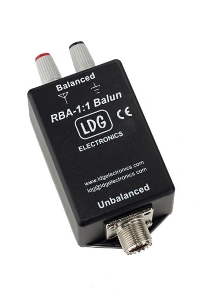
The solution is a 1:1 choke balun such as the LDG RG1-1:1 balun below. It’s designed for connecting window line to coax and can handle 100 W. You can make your own out of ferrite cores or even by coiling up the coax to form an inductor. Both techniques are discussed in the ARRL Antenna Book.
Other Cool Transmission Line Stuff
Speaking of the Antenna Book, the chapters on Transmission Lines and on Transmission Line System Techniques have plenty of other know-how to share, such as:
- Changing a short or open to a pure reactance with 1/8-wavelength line sections
- Impedance inversion by quarter-wave lines
- Quarter-wave synchronous transformers
- Using transmission line stubs as filters and for impedance matching
Once you start understanding the tools of working with feed lines, all kinds of interesting techniques open up. You’ll also have a much better understanding of why antenna systems behave the way they do and how to use that behavior to your advantage!