
Operating portable is always a challenge, particularly with HF antennas that are usually close to the ground and quite a bit smaller than a full quarter- or half-wave. Verticals, especially base- and center-loaded models, are very popular, for example. Loaded horizontal dipoles on a tripod and small transmitting loops are also common. These antennas are relatively small, don’t require high supports, and are easy to set up, but their performance can be disappointing.
Recently, the idea of rolling out metal mesh under the base of these small verticals has caught on. Use of a “magic carpet,” as it is sometimes called, is reported to increase transmitted signal strength by an S unit or even more. What’s going on? How does this work? What’s the best way to use the mesh and are there drawbacks?
Vertical Antennas Make Vertical Fields
Let’s look at the most common way to use the mesh: under the feed point of a ground-mounted vertical antenna. Because the antenna is oriented vertically, the RF field it radiates is vertically polarized. This means that the electric field created by the antenna is oriented vertically. Any electrons in that field will try to move in the direction of the electric field—up and down.
The electric field doesn’t end at the surface of the ground. The same vertically polarized field causes current to flow in the soil (or whatever is below the antenna). In addition, the total field from the antenna creates return currents that eventually flow back to the feed point. So, the complete circuit of the antenna begins with current at the feed point, extends through the air and soil around the antenna, and returns to the feed point. (See the chapter “Effects of Ground” in the ARRL Antenna Book for a complete discussion of vertical antennas, ground loss, and ground radial systems.)
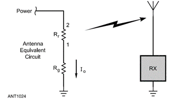
The equivalent circuit of an antenna connected to a receiver (RX) showing the antenna’s radiation resistance (Rr) and the ground loss resistance (Rg). (Graphic from the ARRL Antenna Book, 24th edition, courtesy of the ARRL.)
This is sometimes described as the antenna having a “missing half” below the surface of the ground. That is a good model for understanding what’s happening. It’s as if a full-size half-wavelength dipole was half-buried in the soil with the center feed point at the ground’s surface. Another way of looking at it is currents in the ground creating a mirror-image of the real above-ground part of the antenna. Either way, you have real, actual currents flowing in the ground—i.e., dirt.
A lot of the energy in fields that create return currents in the ground is lost as heat and doesn’t create waves that travel away from the antenna. It’s the same as putting a resistor in the path of the current. Some RF flows along the surface of the ground, too, but it is also quickly dissipated. Without some means of reducing the loss, about half or 3 dB of the transmitter power would be consumed in ground loss. Obviously, this is not desirable!
Reducing Ground Losses
Vertical antenna users can use several techniques to reduce ground loss. The most obvious is to install the antenna over dirt with lower resistance. For example, wet soil or water makes a much better ground than dry or rocky dirt or a parking lot. If you have this option—say, placing the antenna near a pond or stream—you will reduce ground loss. Salt water can be even better.
Another option might be to raise the antenna above the ground. This reduces the strength of the electric field that makes electrons move in the soil. You will still have to provide a path for the current to get back to the feed point and that complicates the installation somewhat, but there will be lower losses in the soil. Mounting the antenna on a metal fence or structure is a typical way of reducing ground loss.
Finally, you can simulate “better dirt” by shielding the antenna from the soil with a ground screen. The screen can be made of any conductive material—wires, sheeting, and mesh all work well. This is the function of your vehicle’s roof or trunk under a VHF/UHF whip—providing a low-loss surface extending about one wavelength in all directions for current returning to the antenna feed point. This would take quite a lot of sheet metal at HF (66 feet around a 20 meter antenna!) so other methods are used.
About Those Radials
The usual practice for ground screens is a set of radial wires connected to the ground terminal of the feed point, stretched out in all directions (radially, thus the name) around the antenna. The goal is to provide a low-loss path back to the antenna’s feed point that doesn’t involve dirt.
There is a fair amount of confusion about radials: Are they resonant? (No.) Should they be one-quarter wavelength long? (It doesn’t hurt but they’re not tuned.) Do they tune the antenna? (Somewhat, but that’s not the function of radials on the ground.) For use as a ground screen the most important thing is that there are a lot of them! (Elevated radials are sometimes used but not usually in portable operation.)
The function of radials on or very close to the ground surface is to provide a low-resistance path for current back to the feed point. Otherwise, the current will have to flow in the dirt, and we know that is a lossy path. It follows that there should be a lot of radials where there is a lot of current—close to the feed point ground terminal where all of the current paths eventually come together. The most important area for reducing loss is within 1/8th wavelength around the feed point. Even many short radials in this area will make a big improvement in reducing ground loss. Longer radials also reduce loss but not as much as those close to the antenna.
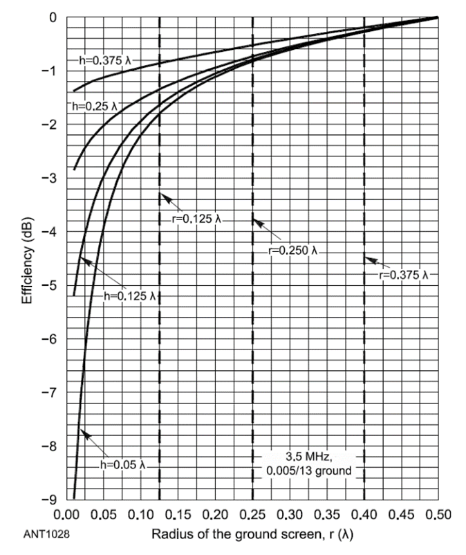
The figure above shows the change in efficiency for an 80 meter vertical as the radius of the ground screen is increased. Even for electrically short verticals (h represents height in wavelengths), most of the improvement is obtained for a radius of 1/8 wavelength. (Graphic from the ARRL Antenna Book, 24th edition, courtesy of the ARRL.)
The Magic Carpet
If you evaluate ground loss versus number of radials (see the ARRL Antenna Book), you will find that at least 16 radials are needed for good ground loss levels. Unfortunately for portable stations, more than a dozen radials are hard to maintain and deploy. They get tangled and snarled, take a while to lay out, and present a trip hazard to people (and animals).
A better solution is to put all the wires into a grid or mesh that keeps its shape, then connect that mesh to the feed point. Galvanized chicken wire and hardware cloth fit the bill perfectly. Both come in rolls that are easy to lay out and roll back up. They provide a LOT of wires in that crucial area under and around the antenna feed point, too. Because the wires are so densely packed, they do a great job of keeping current out of the soil.
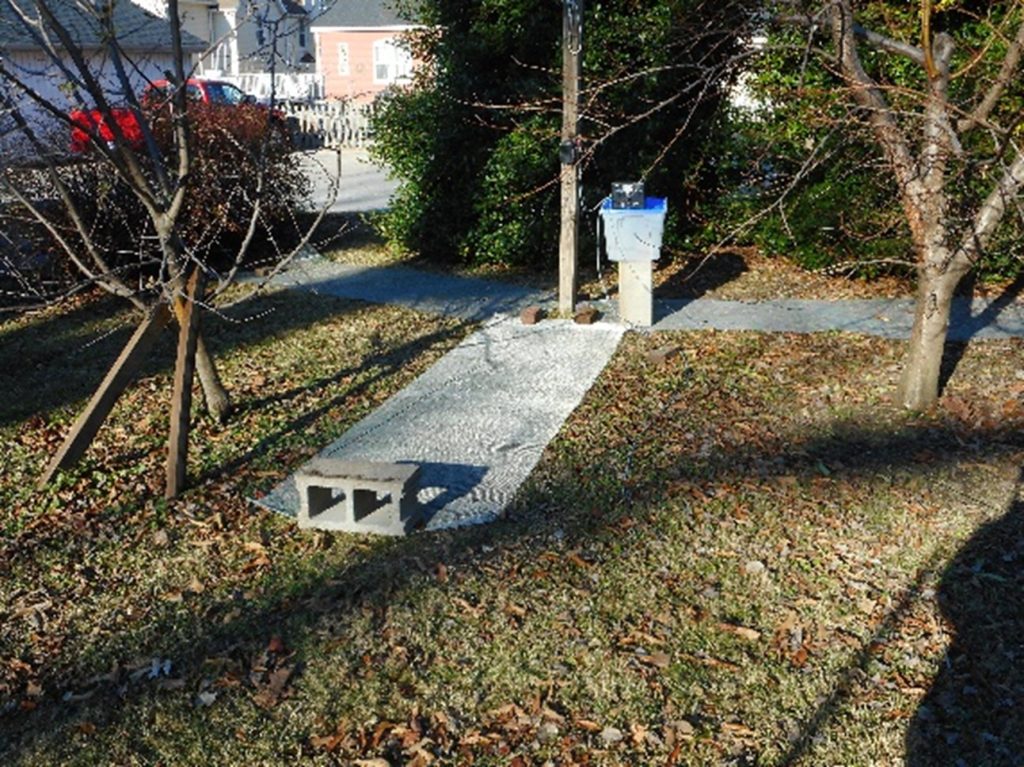
Three 10-foot rolls of hardware cloth serve as a ground screen around this end-fed antenna that has been converted to a ¼-wave vertical.
How big should the ground screen be? As mentioned earlier, mesh within 1/8th of a wavelength around the antenna will do a great job of reducing ground loss. How many rolls do you need? Even one roll of mesh will make some improvement. Having rolls in three or more directions around the antenna will be even better. Six rolls (or three long rolls stretched out on either side of the antenna) is about the practical limit. Hold the mesh down with weights such as handy rocks or sticks. It is not necessary to connect the mesh to the soil. By itself the mesh may be enough to allow the antenna to operate well. However, for the lower HF bands (7 MHz and below), you may want to run a few longer radials out to cut ground losses farther from the antenna.
Do I connect the mesh to the feed point? Should the mesh rolls be connected together? Yes to both questions! While laying the mesh rolls on top of each other will work, connecting them together makes the screen sturdier and improves the electrical connections. Split bolts, usually used for ac electrical ground connections, work just fine at RF, too.
Use a pair of pliers to enlarge a hole big enough for the bolt halves to pass through the mesh layers, then tighten the nut. Add a heavy wire from one or two of the bolts to the feed point. The photos below show examples of how to do this.
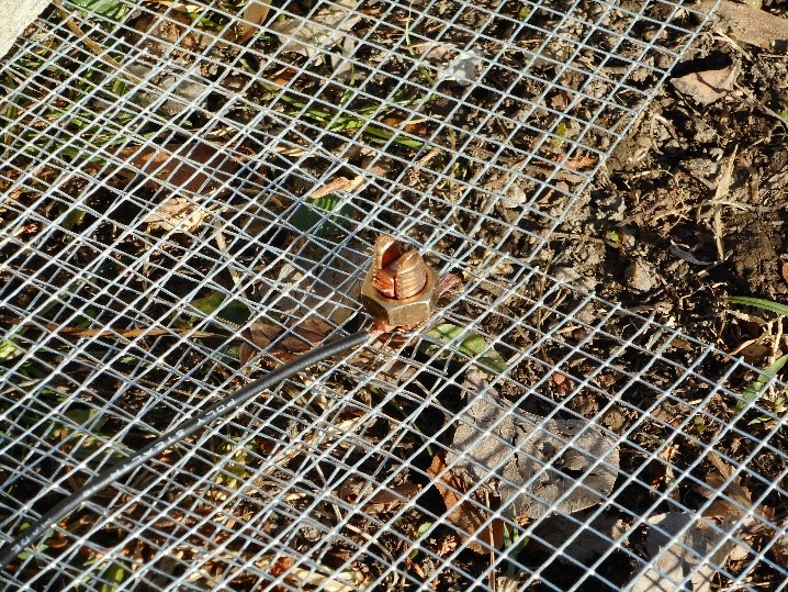
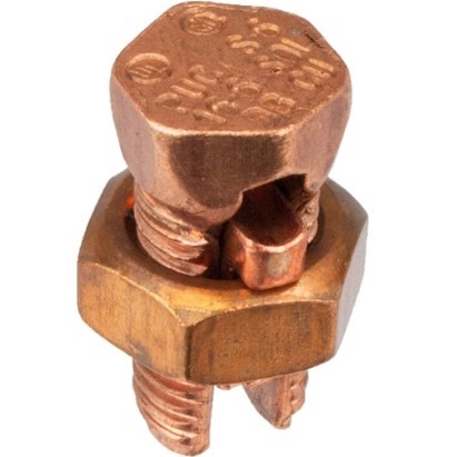
A split-bolt from the electrical section of a hardware store is used to connect mesh sections together and attach a ground wire that connects to the antenna feed point.
What about using the mesh under horizontally polarized antennas such as Buddipole dipoles or under small transmitting loops? Don’t connect the mesh to the feed point of these balanced antennas. Connecting them to the ground screen will disrupt how they work. Just place the mesh under the antenna. The large area of the mesh will affect the tuning of these antennas, however.
Ground Screens and SWR
After adding a ground screen, you should notice a change in the antenna’s minimum SWR. If the ground loss resistance (Rg in the schematic above) is very low, what’s left is the radiation resistance (Rr) of the antenna by itself. A perfect 1/4-wave monopole vertical has a 32Ω radiation resistance, which represents the work done by the antenna to radiate the applied power as RF waves. This results is an SWR of 1.6:1 to 50Ω feed line. You may have tuned and adjusted your antenna for an SWR of 1:1 before using the mesh but that also includes ground losses, so increasing SWR with the mesh is a good thing! It is possible to lengthen your antenna a little bit to increase Rr and bring SWR back to 1:1. However, leaving the SWR at 1.6:1 or so is just fine and you’ll experience very little degradation in performance.
Getting a “Free” Band
For those of you using End-Fed Half-Wave (EFHW) antennas, you can get an “extra” band from the antenna with a mesh ground screen. On its lowest band, an unloaded EFHW is 1/2-wavelength long. That means at half the frequency it will be 1/4-wavelength long and can be configured as a ground-plane vertical if the feed point is near the ground. For example, a 40-10 EFHW can be made to work on 80 meters and an 80-10 EFHW like this one will work on 160 meters as shown in the backyard photo above displaying rolls of stretched-out hardware cloth.
Add the mesh under the antenna feed point as shown in the same photo. Additional radials extending beyond the mesh are helpful, too. Three or four 10-foot rolls of mesh are usually sufficient. If you leave the mesh in place for a permanent installation, it will probably affect the antenna tuning somewhat.
Disconnect the antenna from its impedance transformer and connect it directly to the feed line. The shield of the feed line should connect to the mesh ground screen and any radials. You may want to use an antenna tuner right at the feed point to keep feed line SWR low—that’s what is to the right of the antenna feed point in the photo. No matter how you do it, though, you just got a free band from your EFHW without changing anything about it!