
Over the past few years, a lot of attention has been developed regarding grounding and bonding. I am pleased that my ARRL book Grounding and Bonding for the Radio Amateur has generated a lot of interest. This is a very important subject for hams as they build stations, install new equipment, and troubleshoot various problems, particularly RF interference or RFI. However, as I observe and take part in online conversations, it is clear that confusion exists about ground connections, bonding of equipment, and their effects on RF and RFI.
This short article focuses on grounding and bonding when dealing with RFI in a fixed (home or stationary portable) HF station. AC safety and lightning protection are closely related but let’s defer those topics to the grounding-and-bonding book. Let’s start by getting the definitions straight.
Definition and Myths of Grounding and Bonding
The word “ground” is overused and often misused. Ground can mean a specific thing (a noun), such as a connection to the actual Earth or a common reference voltage. Ground can be a type of thing (an adjective), such as a ground wire or a ground plane. Ground can also be an action (a verb), such as when a capacitor is discharged by a grounded safety interlock. So, we have to be very careful with the word “ground” to be sure we’re all talking about the same thing.
There are a lot of myths about “ground” and “grounding” that arise from confusing the definitions or frequency ranges or desired effects. Here are four common ground myths:
- The Earth is NOT a sink into which we can pour RF and expect it to disappear. The ground surface and the connection to it have widely varying voltages and impedances at different frequencies.
- “RF ground”—It’s very hard to maintain a “zero volt” difference over a wide frequency range. What might be possible is a small area that has the same voltage over a modest range of frequencies but within fairly narrow limits.
- “Ground loops” can result in hum or buzz, but that is primarily an audio or power-frequency issue, not RF. Any conductive path forming a loop between at least two pieces of equipment is a ground loop and even modest amateur stations usually have many. These can’t be eliminated, so the voltages generated in them must be managed.
- “Single-point ground” refers to an electrically-small point used as a reference voltage or common current return point. At ham-band frequencies, “electrically small” covers from a dozen feet down to centimeters. Trying to tie every piece of RF equipment to one physical point in the station often creates loops with long conductor lengths, causing more problems than it solves.
It’s no wonder that hams are confused!
Bonding is a connection intended to keep two points at the same voltage so that the connected equipment goes up and down in voltage together. Minimizing voltage differences between pieces of equipment (even the ones that don’t have a power connection) accomplishes the following:
- Prevents shock hazards and RF burns caused by voltage differences
- Prevents destructive voltage differences caused by lightning surges and strong RF fields
- Limits current between devices caused by RF voltage differences, this article’s main topic
Bonding sounds complicated and expensive, but it is really very straightforward. You must use the right materials as discussed below and make the bonding system as complete as possible.
RFI from Common-Mode Current
The primary cause of RFI in ham station equipment, including non-RF audio and computer gear, is RF current getting into circuitry where it should not be or at least is not expected to be. Most of the time, this current is common-mode current that flows on the outside of a cable shield or on all of the conductors in a multi-conductor cable. This is different from differential-mode signals that flow on pairs of conductors, such as twisted-pair cable or inside coax. (Remember that due to the skin effect, the inside and outside surfaces of cable shields can act like completely different conductors.)
Current only flows because there is a voltage that exists between two points. Without the voltage, there is no current. So, by minimizing voltage differences between pieces of equipment around your station, you can also minimize common-mode current flowing between them. That is the RF benefit of bonding in your station—minimizing voltage differences and the resulting current. For the purposes of minimizing common-mode current, it doesn’t matter if the bonding conductors are connected to an ac safety or lightning protection ground at all. (They should be, of course, but not for reasons of minimizing RFI.)
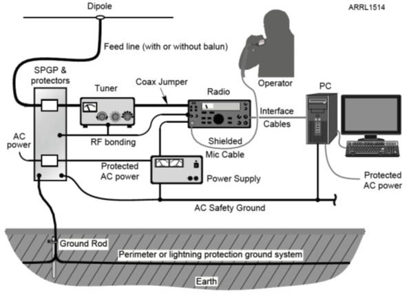
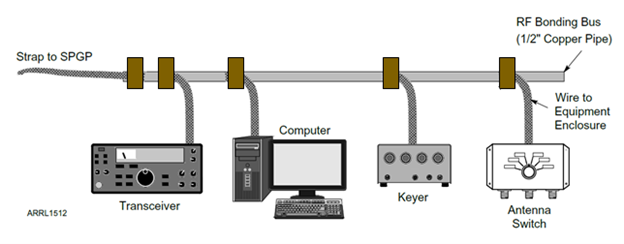
Where does the voltage come from? Mostly it comes from your own transmitted signal which is very strong in your station. Even a 100-watt transceiver will cause plenty of current to flow in a station if the antennas are close by. Consider that for typical city or suburban lot sizes, your station will be in the near field (just a wavelength or two from the antenna) of most HF antennas. As shown in the drawing below, EVERYTHING in your station will pick up RF as voltages and currents on and between pieces of equipment. Even you, being somewhat conductive, are picking up RF, too.
Bonding in the Station to Minimize RF Voltage and Current
The strong RF field (stronger if you use an amplifier) is why you bond everything together. You want to minimize any common-mode current flowing between pieces of equipment. You also want to minimize “hot spots” in the station that can cause RF burns.
For bonding to work at RF, the connection has to have a low impedance and it must be electrically short—no greater than 1/10th of a wavelength and preferably much shorter at the highest frequency of interest. This prevents current in the connection from creating voltage drops and acting like a transmission line. For example, a piece of wire ¼-wavelength long will act like an open-circuit on one end and a short circuit on the other!
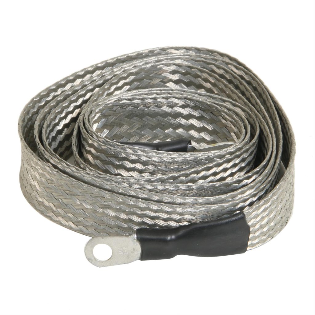
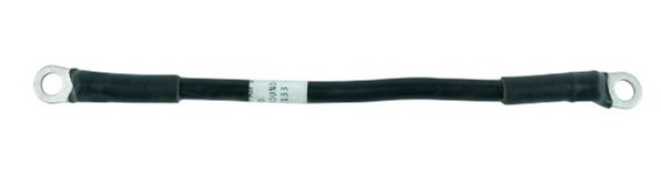
Keep bonding connections short and direct using heavy wire (#12 or #14 AWG solid or stranded wire is fine), solid 20-gauge metal strap, or flat tinned woven braid (see photos). Be sure to use toothed lockwashers (either internal or external tooth) when making a bonding connection. If the braid is used in a vehicle or exposed to moisture, it must be protected by a waterproof coating or sleeve.
A bonding bus has been a popular technique at RF for bonding and grounding for many years. A piece of copper or aluminum pipe or angle attaching to the operating position is inexpensive and works well. Connect equipment to the bus with short, heavy wires attached to screws or terminals on the bus. (Don’t use hose clamps—they aren’t designed for metal-to-metal contacts and loosen over time.) Ground-rod clamps will work on copper pipe, too. (Graphic courtesy of the American Radio Relay League)
A reference plane can be created from metal flashing, screen, or mesh placed under your equipment at the operating position. For portable stations, such as at Field Day or POTA activations, aluminum foil is lightweight and can be recycled afterwards. If you have equipment on multiple shelves, be sure to bond all of the reference plane sheets together.
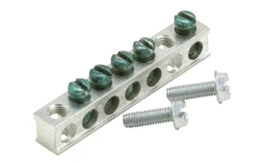
A reference plane helps minimize voltage differences at RF by creating a very low-impedance conductor along the length of the operating position. A bonding bus can be attached to the reference plane. Ground bars (see photo) that are used for ac service ground and neutral connections can be attached to the reference plane as well.
Once you’ve established the bonding bus or reference plane, be sure it is bonded to the ac safety ground, your lightning protection ground, any perimeter ground system outside your residence, and the single-point ground panel (SPGP) where feed lines and other cables enter your station.
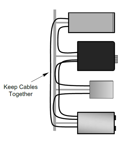
As the drawing below suggests, run all of your cables together along the bonding bus or directly on the reference plane. Most signal cables are a few feet long and that makes them an effective receiving antenna in a strong RF field. Use the shortest cable you can (all cables must be shielded except for dc power and ac line cords) and coil up any excess length. (A figure-8 coil minimizes inductance.) This minimizes the length of the cable exposed to the RF.
What about ferrite snap-on or toroid cores? These are also very helpful, especially where bonding is difficult or the cable in question simply picks up a lot of RF due to length or placement. Have the right type of ferrite for the RF current frequency range. The two most common mixes are Type 31 for HF and Type 43 for VHF and above.
The Results of Bonding
Once you have established a bonding system in your station, you should notice that installing new equipment or moving existing equipment does not create new RFI problems, hot spots, or other annoying RF gremlins. SWR and other RF measurements will be affected much less when you touch or adjust equipment. Your transmit audio on voice or digital data modes is likely to have less noise and power-frequency artifacts (buzz and hum). If you do experience interference (from a noisy switch-mode supply or computer network cable, for example), it will be easier to isolate and resolve the problem.
These techniques can also be applied to home entertainment and audio systems, computer and network equipment, home automation systems, and other assemblages of electronics that experience RFI.
The same bonding philosophy of keeping equipment at the same voltage (whatever that voltage is) and minimizing current flow between equipment also works in your favor for ac safety grounding and for solid lightning protection. One well-constructed system is all you need!