
A dipole is the go-to antenna for many hams, but why is it so popular?
Beacause it’s an inexpensive, yet effective antenna you can build yourself using wire, insulators and rope that you may already have in your junk box. Plus, you’re not just limited to one band. You can enjoy the benefits of multiple dipoles on different frequencies, connected at a single point, and use only one feedline. These multiband antenna combos are commonly known as fan or parallel dipoles.
How it Works
The way in which HF multiband parallel/fan dipoles operate is each dipole presents a low impedance at the feedpoint on its resonant frequency. As the signal frequency moves away from the resonant frequency of one dipole, its impedance increases and it does not radiate power. But at the resonant frequency of another dipole, the impedance drops and it will take power at the feedpoint.
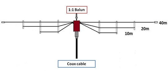
Each element will radiate as a resonant dipole on its own frequency, making this an easy way to provide multiband capability on a number of different HF bands. In the figure below, the first element is tuned for 40 meters, the second for 20 meters, and the third for 10 meters. You get three bands in the space occupied by a single-band antenna.
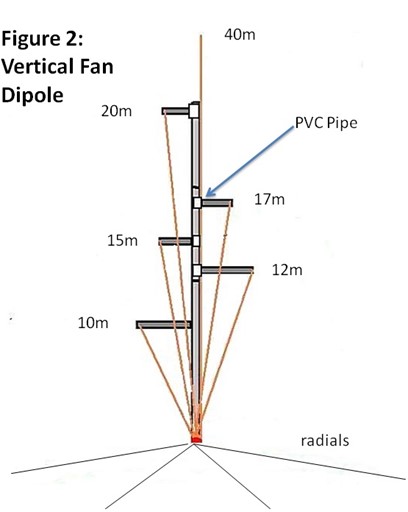
Limited space? You can make a quarter-wave vertical version, as shown below. Like all verticals, it will need a radial system.
Multitasking With Dipoles
Making a fan/parallel dipole is a relatively easy way to create a resonant multiband antenna by building several individual dipoles. Cut the elements a little longer than estimated using the standard quarter-wave formula: Length = 234/MHz. Except for the longest dipole, the others need to be a few percent longer to resonate properly. This is likely due to the result of additional capacitance caused by coupling to the dipole elements running parallel.
The next step is adding a center connector and creating a support system for the wires. Typically, small diameter PVC pipe (½”) is used as a separator because it’s easily available and can also be utilized for end insulators. For parallel dipoles, 5-6″ should be sufficient separation between elements. However, more separation provides less interaction between elements and easier tuning.
Keep in mind that dipole elements do not have to be exactly parallel. Another strategy is to spread the elements out like spokes from a wheel as shown below.
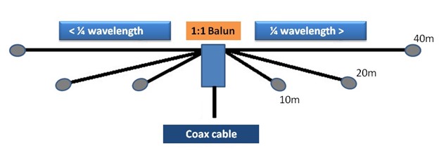
One example for 40 and 80 meter elements is to spread the 80 meter dipole north to south and the 40 meter elements east to west. This gives you 90 degrees of separation between each element. For three dipoles, use 60 degree spacing, and so on. When using the fan configuration, it’s necessary to have a number of different anchor points—one for each end of each dipole. They can be deployed as a flat-top (horizontal) or an inverted-V, depending on the installation.
As with any type of dipole, don’t expect a low radiation angle for DX unless you get the antenna significantly above ground in terms of wave length. Also, since this is a balanced antenna, the use of a 1:1 balun is recommended if you feed it with 50-ohm coax.
One of the keys to successful builds is not to add too many bands. Many hams have found that three band versions work very well and can provide excellent performance. Adding more bands may complicate tuning.
Tuning
Tuning is done much like any other dipole. Elevation affects SWR, so hoist the antenna all the way up for measuring, then lower it to make any necessary adjustment. Adjust both sides equally. Check out my earlier OnAllBands blog, “Tuning Your Dipole Antenna Installation” for additional tips.
Order makes a difference with fan/parallel dipoles. Begin with the lowest frequency band first and work progressively to the highest frequency band. The effects of interaction between the elements will have some effect, but shouldn’t cause enough problems to worry about.
Sometimes adjusting the lengths can be a challenge if the dipole has many sections covering different bands. Two or three dipoles connected to the same feeder can be easily adjusted. However, going beyond three dipoles can test your patience.
Ready-Made Options
Maybe you don’t have the time or materials to make your own. There are several commercially-made models you can purchase for a variety of different bands that are fully assembled and require minimal or no tuning.
Alpha Delta Parallel Dipole Antennas (DX-CC, DX-DD, DX-EE, DX-LBPLUS) have been available for at least 30 years and are very popular. They use a “hybrid” approach in their DX-CC model—an ISO-RES coil is connected to the 80/40 meter wires, and separate parallel wires are used for 20 and 10 meters—all separated with spacers. The coil provides 80/40 meter coverage on the top element and reduces the overall length to 82 feet. For the 15 meter band, it uses the third harmonic of the top 40 meter section. Since resonance for 15 meters would be at the upper portion of the phone band, a tuner is needed.
Chameleon’s CHA 40/20 FD Fan Dipole covers two of the most popular bands, 40 and 20 meters. It includes full-length antennas connected to a common feedpoint. A wide-range antenna tuner will also enable operation on the 17, 15, 12, and 10 meters. The easiest way for field or permanent deployment of this antenna is to set it up as an inverted-V.
The Kelemen 11520-D84H fan dipole provides coverage for 40 and 80 meters using a complete dipole for each band connected to a common feedpoint. It’s recommended configuration is an inverted-V for best results. EAntenna Multi-Band Dipole Wire Antennas (EA10152040DXS, EA1015204080DXS, EA121730+6DX, EA4080DXS) are configured in parallel with spacers, similar to the Alpha Delta models. They also use a coil on the lower band wire for 80/40 meters