
Portable operating—in parks, on islands, atop summits—has become delightfully popular over the past few years. It’s not hard to figure out why, either. You get to combine visiting new places, physical activity, and the thrill of being a sought-after contact! Portable operating can mak a very effective substitute for a home station if you are limited by restrictive covenants or lease agreements, lack of space, or high local noise levels. As the baseball adage goes, “Hit ‘em where they ain’t!”
Given the high quality of today’s transceivers, the most important station component is the antenna system that starts at the RF connector of your radio and ends a wavelength or two away. Gains and losses anywhere in the system affect signal strength. As has been said, a dB is a dB is a dB (K7GCO), so wherever you can gain (or avoid losing) dBs helps your signal be louder there and their signals easier to receive here. (Except as noted, antenna “radiation” refers to both transmitting and receiving.) Improvements help on both receive and transmit, and that is the subject of this article.
Let’s start with the antenna itself. Everybody wants to know, “What’s the best antenna?” There isn’t just one answer, but perhaps the most useful answer is “the one you can put up that works other stations!” There are too many different circumstances of portable operating to pick even a few, but there are some guidelines that will help, no matter what kind of antenna you choose.
The Straight Part Radiates
For the most common antennas, nearly all of the antenna’s radiation or reception comes from the straight sections of wire or tubing. It doesn’t matter if the antenna is vertically or horizontally polarized. The various tricks we use to make an antenna seem bigger electrically contribute little to the actual radiation. A loading coil or capacitance “hat” or folded sections (linear loading) only serve to increase the antenna’s effective electrical size and don’t affect the parts of the antenna that radiate except to redistribute current on them.
Choosing the antenna involves a lot of tradeoffs: size, weight, expense, ease of installation, complying with site rules, and so forth. If you have several antenna choices, it is usually true that the straightest antenna will be the most effective. For example, the simple half-wave dipole remains the best ham radio bang for the buck as it has since it was first used by Hertz to discover electromagnetic waves in the 1880s. Correspondingly, the quarter-wave vertical monopole (with a good ground screen as discussed next) is also hard to beat. Antennas made up of radiating straight sections like Yagis, half-squares, full-wavelength quad loops, etc. also work quite well.
Minimize Ground Losses
If you choose a vertically polarized antenna, especially a quarter-wave ground-plane design, ground losses can really eat up a lot of signal. Why? The radiated electric field component creates return current flowing back to the feed point through the very lossy soil below and around the antenna. That is why the ground screen is so important: it provides a low-loss path for return current instead of heating up the worms!
It is not enough to just lay out a few radials and trim them for a resonant feed point impedance. You must use multiple radials to create enough low-loss current paths to reduce ground loss: at least eight and preferably 16 or more. An even better choice is a roll or two of hardware cloth or chicken wire at the antenna’s base. Anything you can do to give return current a low-loss path back to the feed point, especially within about one-tenth wavelength around the antenna, will improve your signal.
Note that radials are not cut to the usual quarter-wavelength of a dipole leg or vertical whip. When laid on the ground the loading effects of the soil coupling to the radial make them look electrically longer than their physical length. A good radial length is about 70-80 percent of their free-space resonant length. Because of the strong coupling to the ground, they don’t behave as a resonant conductor in the usual sense. (See the “Effects of Ground” chapter in any recent ARRL Antenna Book edition for a more complete explanation of radials.)
Does ground loss not occur for horizontally polarized antennas? It is much less a factor because the signal’s electric field creates current that flows along the surface instead of in the soil. As the horizontal antenna is lowered, these currents can become strong enough to create equal-and-opposite currents in the antenna. In effect, this acts to short circuit the actual antenna, lowering its feed point impedance dramatically at very low heights. Horizontal antennas at a quarter-wavelength or higher have much lower ground losses than a typical ground-mounted vertical. If such a horizontal antenna is practical, you’ll probably have good results. Have both a vertical and horizontal antenna in your toolbox to take advantage of whatever your operating site allows.
Loading Coils
One of the most common methods for making a short antenna, such as a common whip, resonate at low frequencies is placing a loading coil in the antenna. While the loading coil does very little radiating, selecting where it is placed in the antenna and how it is made have big effects on how the antenna performs. Remember that the straight parts of the antenna do the radiating.
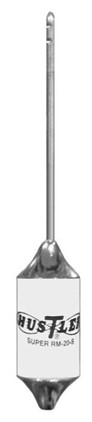
After much analysis and experimentation, it was determined that the best place for a loading coil is about in the middle of the whip, known as center loading. This is a good tradeoff between how much inductance was needed (less toward the base and more toward the end) and mechanical sturdiness. The popular Hustler designs, as shown in the image below, have a heavy base mast section topped with a coil (a.k.a. “resonator”) and a short stainless steel whip. The base section is what does most of the radiating.
Placing the coil at the base (base loading) also resonates the whip, but current in the coil is higher instead of in the straight part above the coil. The popular Hamstick-style mobile whips act as base-loaded whips on the lower HF bands, changing gradually to a more center-loaded configuration on the higher HF bands.
Higher coil current creates more losses in the coil according to I2R. This is why coil construction is so important. The coil should be made out of large diameter wire or even tubing for the maximum surface area. Remember that RF current flows on a conductor’s surface due to the skin effect. That also makes the coil material important. Of the most common materials, copper has the least loss, followed by tinned copper, and then stainless steel. Similarly, making contact to the coil, if it is adjustable, requires use of a low-resistance clamp or clip. Sliding contacts are particularly susceptible to overheating and can become very lossy.
Capacitance Hats
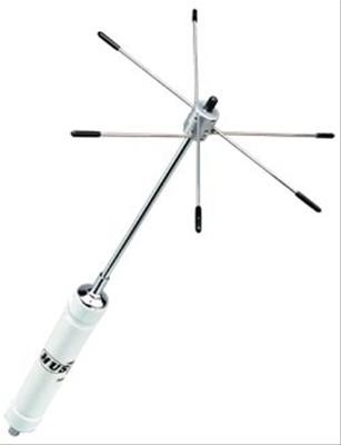
Capacitance hats must be located at the top end of the whip to have the most effectiveness. The goal of the hat is to increase current in the straight part of the upper whip. There are significant mechanical challenges capacity hats have in mobile antennas, but for portable antennas that don’t move, clip- or clamp-on wires and rods work fine. The image below shows the “Hot Rodz” capacity hat attached to a Hustler resonator coil.
Some designs place the hat at the top of a center-loading coil which is sturdier but less effective. Remember that the outer end or edge of the hat will be at high voltage, even for low power, so keep away from it! (Don’t ask how I learned this important fact.)
For non-mobile (immobile?) antennas, capacitance hats can be created simply by clipping lengths of wire to the antenna at or near its top. The wires do not need to be symmetrical around the antenna. A good trick to using a loaded whip on both 80 for CW and 75 for phone is to tune the antenna for the phone band and then experiment to find the length of capacity hat wire (or wires) that lower the resonant frequency to the CW frequency. You may be able to make this work on a mobile whip as well, but be sure the extra wire is securely attached.
Match at the Antenna
While it’s convenient to place antenna tuners at the transceiver or use the built-in tuners, remember that SWR in the feed line will not be changed. For high SWR values, this can lead to significant losses in longer feed lines. To get an idea of how much loss, make a temporary installation of your antenna and try to measure impedance right at the feed point. Another option is to model the antenna using EZNEC or some other software. Then use a transmission line calculator such as TLW that comes with the ARRL Antenna Book to calculate the resulting loss.
For SWR above 3:1, you may be surprised at how high losses can be! For example, here’s what happens when a 100-foot length of RG-58 is used with an antenna that is quite a bit off resonance at 14.2 MHz. The feed point impedance is 500 + j200Ω, creating an SWR of 11.7 at the antenna. At this frequency and SWR, the additional line loss due to SWR is 3 dB—half of the power is wasted as heat! Also note that the transmitter only sees an SWR of 4.5 because so much of the reflected power is dissipated.
There are two ways of dealing with high feed point SWR. The first is to configure and adjust the antenna such that the feed point impedance is close to 50Ω. Caution—ground losses in vertical antennas can raise the feed point impedance from the zero-loss value around 35Ω (an SWR of about 1.4:1) to make the antenna “look better.” If adding radials also raises the SWR, you may have a ground-loss problem. The second way is to install your matching device, whether it is a shunt coil, L-network, or antenna tuner, right at the feed point. This reduces line loss due to the elevated SWR.
Line Loss Matters
Choose the best quality feed line you can afford or carry. SOTA enthusiasts who carry an ultra-light station to a mountain peak count every ounce, so feed lines require constant tradeoffs between loss and weight. In this situation you might use a good quality RG-174 coax for a short, low-power run. Foam-core cable is lighter and lower-loss than solid-polyethylene types. Buy the good stuff and install it correctly. When packing and unpacking, treat feed lines with care. Avoid nicking or abrading the jacket, too.
With a high feed point impedance such as for an off-center-fed antenna, you might use a length of 300 Ω twinlead and avoid at least one impedance transformer. Use a tool like TLW or SimSmith to model the feed line and find a low-loss solution. For example, using 300Ω twinlead with the 14 MHz antenna discussed a couple of paragraphs ago results in a feed line loss of only 0.1 dB and an input impedance of 156 + j15Ω, creating an SWR of about 2:1 that an internal tuner can handle easily.
Cheap Connectors–Aren’t
Connectors and adaptors are not opportunities to skimp, particularly “barrel” connectors (a.k.a. PL-258). A connector doesn’t have to burn up to be lossy. Check adaptors with an SWR measurement at full power. Be wary if a PL-259 connector’s center pin inserts too easily into an SO-239’s socket. That may indicate poor contact in the socket, leading to overheating and failure. Give each connector a good visual inspection, discarding any with discoloration or corrosion.
Portable stations are frequently assembled and disassembled, so a connector may get quite a few on/off cycles and jumpers get bent, coiled, and yanked on. Inspect all of your “RF plumbing” before heading out to operate and replace any suspect components.
You might be surprised to know that you don’t necessarily have to use an “official” RF connector at HF. For truly lightweight stations, a simple screw terminal and feed line pigtails may be just fine. RCA or phono plugs have long been used at QRP levels with good results. At the 100W level, BNC connectors are just fine and weigh much less than UHF connectors.
Tuners and Transformers
An adjustable antenna tuner can have a surprising amount of loss at high SWR or when misadjusted. Start by reading product reviews (QST has many antenna tuner reviews with ARRL Lab measurements) to compare qualities like loss, especially for high SWR values and tuning range. Once you select a tuner, learn how to adjust it for the lowest loss. Many different settings can produce a 50Ω impedance, but there is usually a much smaller group of settings that minimize loss. Don’t overload the tuner to avoid overheating sliding or rotating contacts, switches, and so forth. A damaged contact may not be immediately noticeable while still causing loss.
Transformers, such as those used for popular end-fed antennas, should be selected to present the lowest SWR to the feed line. It may be helpful to have a couple of different types that span the range of 9:1 to 49:1 or even higher so you have the most efficient available for a particular installation. Most impedance transformers pass the signal through a ferrite core which can only handle so much power. Don’t overload the core or it may heat up and change its magnetic properties, resulting in higher losses.
Terrain and Obstructions
While I have focused on losses thus far, here is a topic that optimizes gain instead. Learn to spot the best “radio location” if you have a choice. A hilltop is often the best choice (and certainly the only choice for SOTA operation!) but sloping ground and drop-offs a wavelength or two distant from the antenna can lower your signal’s elevation pattern dramatically compared to flat ground. Over flat ground, try to choose a spot clear of obstructions or poor soil. Moist ground or locations near water are often excellent choices, particularly for vertical antennas.
For horizontal antennas, try to locate the points of maximum current as high as possible. If you have only one support, orient the antenna with the point of highest current at the top of the support. You may have to compromise if you are using the antenna on multiple bands, but getting the center up in the air is always a good strategy. For end-fed antennas, an inverted-V configuration is often effective.
As I mentioned at the outset, items near the antenna can also have a big effect on your antenna system’s performance. At HF, trees are generally not a problem unless the antenna runs close to and parallel to the trunk. What you should avoid are metallic roofs and siding, metal masts and fencing, and of course, elevated power lines of any voltage. An exception to avoiding metal fences is to use them as a ground-plane for vertical antennas. I have had great success in bolting a vertical to an athletic field fence or backstop or even a barbed-wire fence.
Learn to spot and avoid noise and interference sources. Nearby AM and low-band VHF antenna systems can create serious overload challenges and also produce a lot of harmonics or mixing products that interfere with amateur frequencies. If you are driving to the site, tune your AM broadcast radio to an unused channel high in the band and listen for noise. Power line noise, solar array and generator noise, and battery charging systems can all render a site unusable. If you are operating from a parking lot or campground, choose a site as far from other vehicles as possible.
Be Aware of RF Exposure
I see too many pictures of portable stations operating at 100W levels with the antenna a few feet away. It is easy to exceed the recommended safe levels in pursuit of convenience. This is a particular problem for high-Q antennas such as small transmitting (“magnetic”) loops even at low power because the near field stores so much energy. It is a good idea to use the ARRL RF Exposure Calculator (www.arrl.org/rf-exposure) to find the minimum safe distances for you as an operator and for the general public. Then make a plan to ensure you’re operating safely.