
There is a lot of confusion about baluns—where you need to use one, what the balun is supposed to accomplish, and even what a balun really is! The term “balun” is also used interchangeably with “impedance transformer” (and vice versa) and that’s often wrong, as well. This blog entry will help you understand the difference and when to use each one.
What Is a Balun?
The word balun (BAHL-uhn) is a contraction of “balanced to unbalanced.” Balance refers to the impedance between either conductor of a two-wire feed line (parallel conductor or coaxial cable) and the antenna system’s reference voltage, such as the Earth or a ground plane. In balanced systems, neither conductor is connected directly to the reference. In unbalanced systems, one of the conductors is connected to the reference, which we will call “ground” even if it’s not a connection to the Earth.
The balun’s function is to transfer power between balanced and unbalanced systems (usually a feed line and a load that can be a circuit or an antenna) in either direction. At the same time, it isolates the unbalanced and balanced systems from getting to the balanced system. Any device performing that function is a balun, whether it “looks like one” (whatever that means) or not.
What Is an Impedance Transformer?
This is a little easier: any device that changes one ratio of voltage to current (that’s what impedance is) to a different ratio. An AC power transformer is an impedance transformer that changes AC current at 115 VAC to AC current at some other voltage. The power (current x voltage) is almost the same going in and out of the transformer, less some loss as heat from resistance. Just like baluns, any device that performs the function of changing the ratio of voltage and current while keeping power the same is an impedance transformer. Impedance transformer inputs and outputs can be balanced or unbalanced. If both have a ground connection, that’s an unun transformer. Because of the common ground, an unun cannot perform the functions of a balun.
Can Baluns Be Impedance Transformers?
Yes! This is where things get confusing. Both functions can be combined into one device, such as the 4:1 current balun (described below). There are also products that consist of an impedance transformer device and a balun device packaged in one enclosure. What’s important for you to understand is that there are two separate functions so that you can select the right device or product based on the needs of your antenna system. This article will explain both of them.
What Problem Does a Balun Solve?
Amateurs use baluns to minimize imbalance at antenna feed points and places in antenna systems where unbalanced and balanced feed lines are connected together. Why is balance important? (Baluns are also used in RF circuits, but we’ll focus on antenna systems here.)
Let’s look at the simple dipole antenna. Equal and opposite current in each feed point terminal is important because we want each “side” of the dipole to radiate equally. That creates the familiar donut-shaped radiation pattern. If the currents in each half of the dipole are unequal, then the radiation pattern won’t be symmetrical. The same is true for Yagis, loops, and other symmetrical or balanced antennas.
Imbalance also occurs when a coaxial feed line is connected directly to a dipole or beam— the outer surface of the shield acts like a “third wire” connected to one side of the feed point. (This is explained in detail by EZNEC developer Roy Lewallen, W7EL, in his widely read paper on baluns.
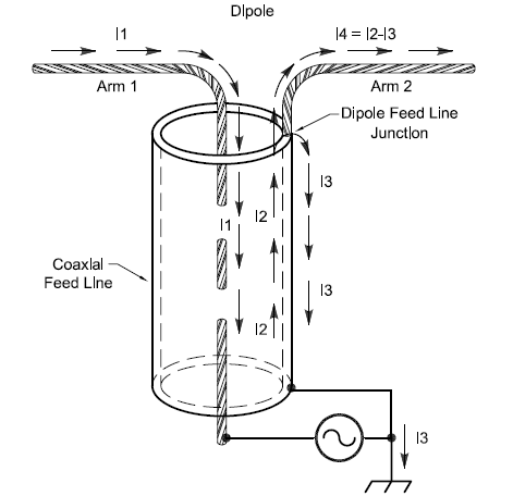
Current flowing on the “third wire” (I3 in the drawing above) means each side of the antenna gets unequal current.
The same “third wire” problem exists when a coaxial (unbalanced) feed line is connected to a balanced feed line. This connection is made as part of the popular G5RV or Extended Double Zepp antennas. To make sure all of the energy is transferred between the feed lines and none escapes on the surface of the coax shield, a balun is required.
Voltage and Current Baluns
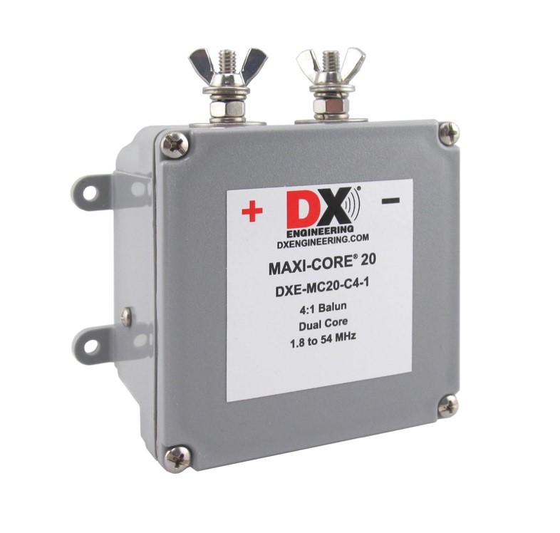
You’ll encounter the terms voltage balun and current balun. A voltage balun, such as DX Engineering’s new Maxi-Core® 20 4:1 Voltage Balun, creates symmetrical voltages between its output terminals. A current balun creates symmetrical currents in each output terminal. If the voltages are symmetrical, aren’t the currents, too? Not if the impedance connected to each terminal is different! This is a very common situation for HF antennas that have one side closer to the ground or some other conducting surface. Since a current balun forces the current in each feed point terminal to be equal, each side of the antenna gets the same current and radiates equally
Choke Baluns
Feed lines can carry both differential-mode signals (with the signal voltage between the conductors) and common-mode signals. With common-mode signals, the current flows equally and in the same direction on both conductors of a parallel conductor line or on the outer surface of a coaxial cable’s shield. To keep the differential-mode signals inside a feed line at the end of the cable, it’s necessary to put a high impedance in the common-mode signal’s path. That’s what a choke balun does—it acts like an RF choke in the common-mode path. (See the ARRL Antenna Book for a thorough discussion of choke baluns. DX Engineering’s new Maxi-Core 20 4:1 Current Choke Balun is pictured above.) Choke baluns are not practical for parallel conductor feed line so the rest of this section only applies to coaxial cable.
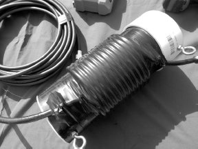
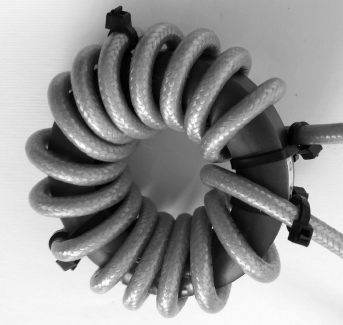
Choke baluns can be as simple as a coil of coaxial cable (see photo above) which increases the inductance of the coiled-up shield’s outer surface. The resulting reactance can reduce the amount of common-mode RF current. This type of choke balun is certainly inexpensive but doesn’t perform consistently over wide frequency ranges or for different coiling techniques. A better technique is to use ferrite for higher resistive impedance over a wider frequency range. Two forms of ferrite choke baluns are popular.
A bead balun consists simply of slipping a number of ferrite beads over the coax. Each bead contributes some impedance and the impedances all add in series. Pictured below is the DX Engineering High Impedance Common Mode RF Choke Kit
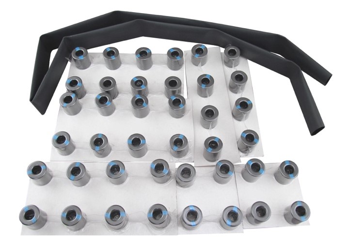
A typical bead balun for use at HF has about 500Ω of choking impedance to block the common-mode signals. 500Ω helps but to really block common-mode current, particularly at high power, you need 3,000-5,000Ω. That means a lot of beads!.
To get these high impedances, a ferrite toroid or rod is wound with multiple turns of feed line as shown in the photo. Solid dielectric insulation, either polyethylene or Teflon, must be used to keep the center conductor in place. The ARRL Antenna Book shows several recommended toroid designs for use from 1.8 MHz through 50 MHz. You can learn a lot more about these chokes from Jim Brown, K9YC’s “Choke Cookbook.”
A single choke balun cannot change impedances between the input and output. This includes the “line isolators” (for example, the DX Engineering Maxi-Core 20 50-ohm 1:1 Feedline Choke) and all types of bead balun. They are only used to block common-mode current. Choke baluns are often combined with impedance transformers to provide both functions.
Flux-Coupled Transformers
A regular transformer which transfers power as magnetic energy through a core—called a flux-coupled transformer—can transform impedances by using different numbers of turns on the input and output windings. Let’s say one winding of the transformer has 4 turns while there are 8 turns on the other winding. Output voltage is determined by the turns ratio (N) of the secondary (or output) winding to the number of turns on the primary. If we connect the 4-turn winding to the power source, N = 8 / 4 = 2:1. The secondary voltage will be N ´ the primary voltage, and primary current will be N ´ the secondary current. Working through the math, the impedance in the secondary circuit is N2 or 4 times the impedance in the primary circuit.
Almost any combination of turns can be used. Flux-coupled transformers with transformation ratios of 2:1, 4:1, 6:1, 9:1, and 16:1 are used for feeding beams and wire antennas such as the popular Off-Center-Fed Dipole (OCFD). The End-Fed Half-Wave (EFHW) antenna often uses a transformer with a transformation ratio of 49:1 (a turns ratio of 7). A tapped output winding allows the ratio to be selected as well. The schematic and photo below show a typical multi-purpose unun transformer.
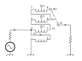
Flux-coupled transformers can have one or both windings connected to ground. The unun configuration with both the primary and secondary connections grounded can be used anywhere along a coaxial feed line or at the antenna if it is also grounded, such as for a ground-plane vertical. If only the primary connection is unbalanced, the transformer is a voltage balun.
An isolation transformer is a flux-coupled transformer with no direct electrical or galvanic path between the primary and secondary connections. This prevents common-mode signals from passing between the input and output connection. The turns and impedance ratios can be any necessary value, although 1:1 is the most common.
Transmission Line Transformers
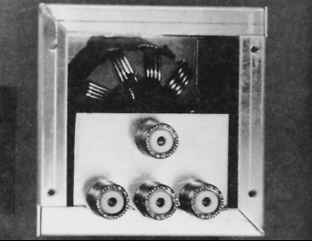
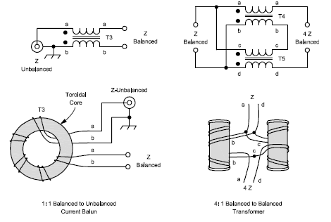
Another type of transformer uses the properties of transmission lines to create different impedance transformation ratios. If the input of the line is isolated from the output, the outputs of two or more lines can be connected in series to increase impedance like multiple secondaries of a flux-coupled transformer. 4:1 and 9:1 transmission line baluns are possible like the 4:1 balun below.
To isolate the input and output of the line, the line is can be wound on a ferrite rod or toroid to create a high choking impedance. This is how 4:1 and 9:1 current baluns are constructed, such as the 4:1 unit below which is constructed from a pair of 1:1 current baluns.
Coaxial cables longer than 1/8-wavelength or so can also be used to create transmission line impedance transformers. These lines have the same “third wire” problem as cable connected directly to antennas. Common-mode current on these transformers can be minimized by paying careful attention to symmetrical arrangement of the feed lines, but in some cases a choke balun is needed. Bead baluns are often used, particularly at VHF and UHF.
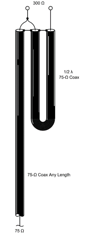
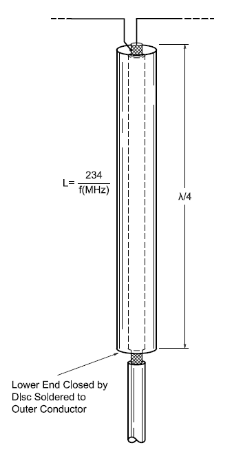
A transmission line ¼-wavelength long changes a low impedance to a high impedance. The sleeve balun shown below uses this property by creating a sleeve around the coaxial feed line connected to the coax shield at one end and open-circuited at the feed point. For the band at which the sleeve is ¼-wavelength long, this is very effective at blocking common-mode current. Sleeve baluns are practical at and above VHF.
Baluns and Impedance Transformers
As you might expect, we’ve just scratched the surface of baluns and impedance transformers. You now know the difference between them, though, so you can make informed choices about what to buy and start putting them to work in your station!
All non-product graphics are used courtesy of the American Radio Relay League from the 24th edition of the ARRL Antenna Book.
Pingback: Baluns vs. Impedance Transformers - Ham Radio News