Posted by Dino Papas
on September 30, 2020 at 7:06 pm
I’ve been a Ham for over 50 years, but up until about four years ago I had never had a QSO on 160m! In 2016, I decided that had to change. This is the story of how I installed DX Engineering’s Top Band “Thunderbolt” Vertical Antenna and went from zero to 160m DXCC in one year.
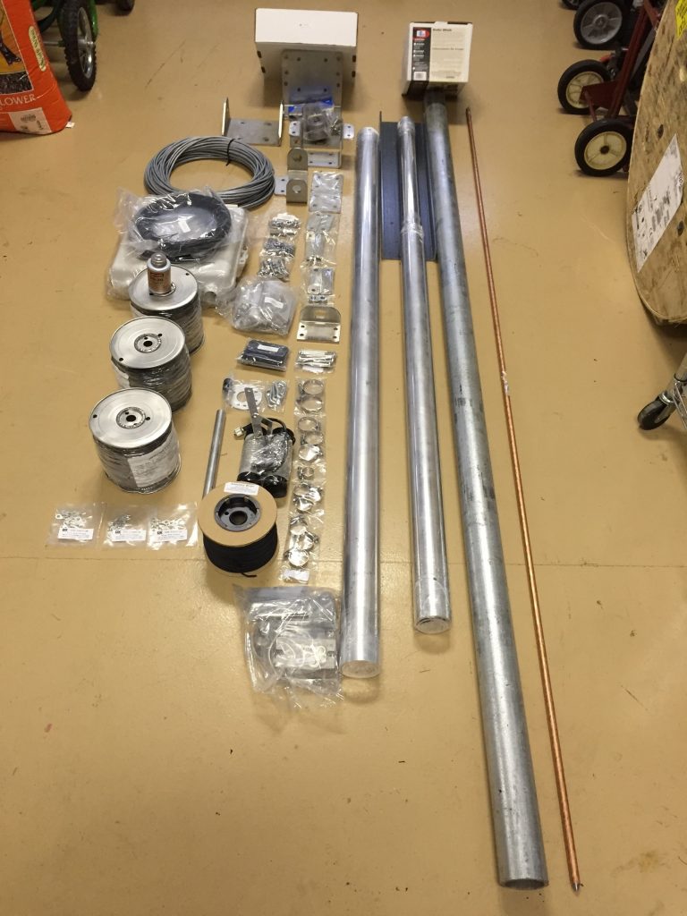
To get started, I worked with Mark Ludwick, W8BBQ, my go-to guy at DX Engineering, for the purchase of the DXE-160VA-1 Thunderbolt Vertical and its appropriate accessories and materials. DX Engineering has several single and dual-band verticals for 160-40m that are top-performing DX machines, and the Thunderbolt was recently spotlighted on the OnAllBands web page. I won’t go into great detail on assembly here, but I thought a pictorial journey of the process would give Hams an idea of how to proceed with a similar project.
Having installed crank-up towers at previous homes, I knew
that I had to dig a hole, fill it with concrete to secure a base for the
antenna, erect the vertical, and lay out an extensive wire radial field.
According to the antenna’s web page and assembly manual:
“The DX
Engineering DXE-160VA-1 is a slow taper 55-foot high Monoband Vertical Antenna
system. The vertical antenna is specifically designed to operate on 160 meters…and
uses a large capacity hat to create a proper match.”
The 2:1 SWR match on my Thunderbolt measured about 50 kHz wide, and as I’m an ardent DXer, was easily adjusted for resonance in the middle of the DX/CW portion of the band centered at 1.830 MHz.
Follow along to see the process:
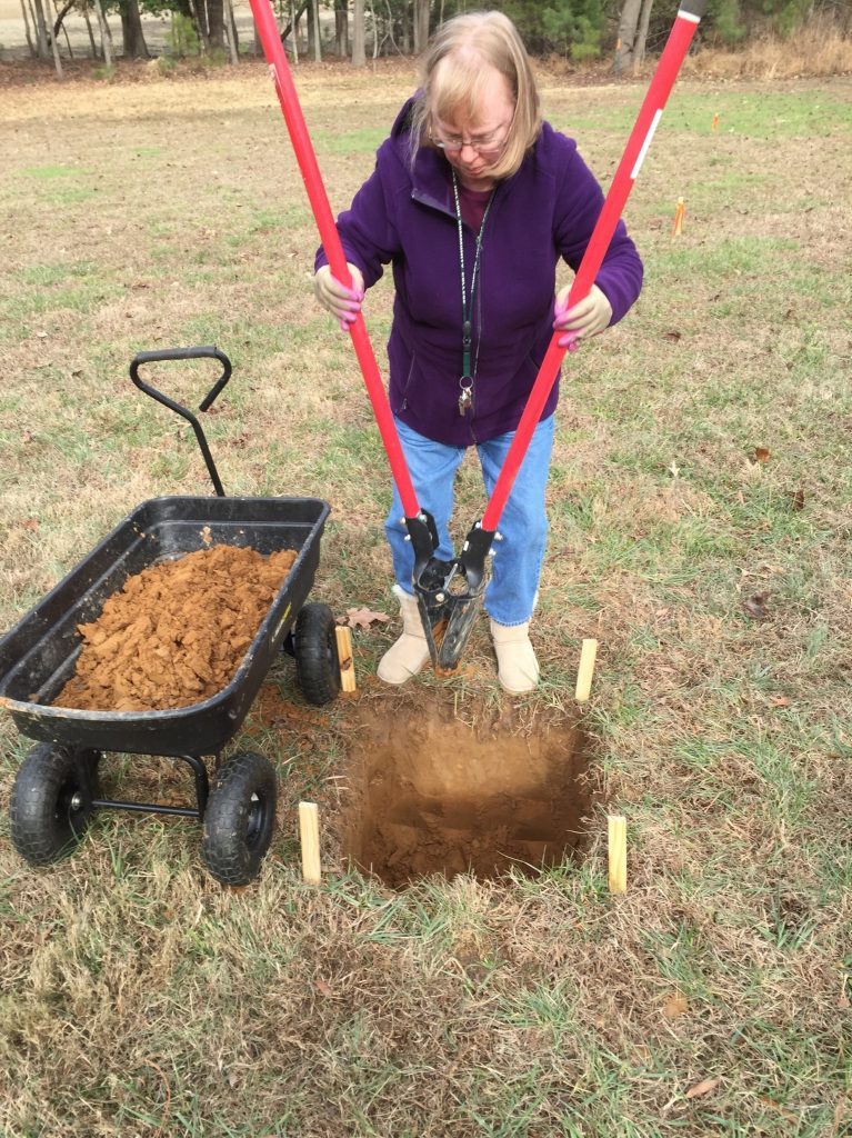
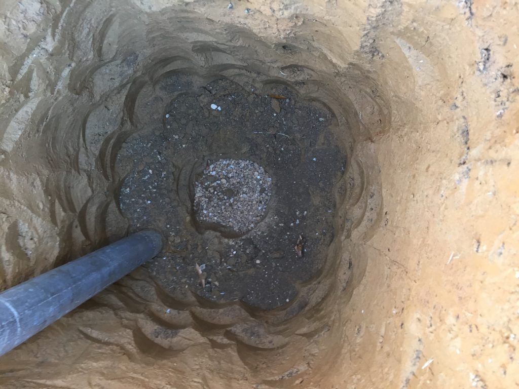
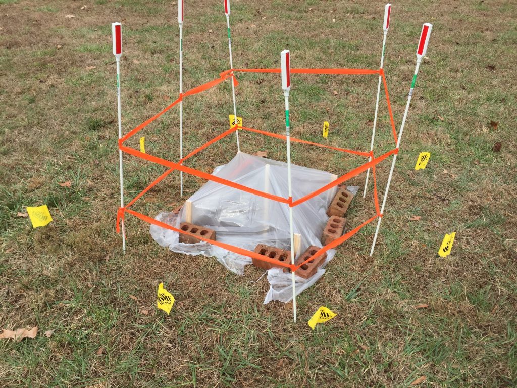
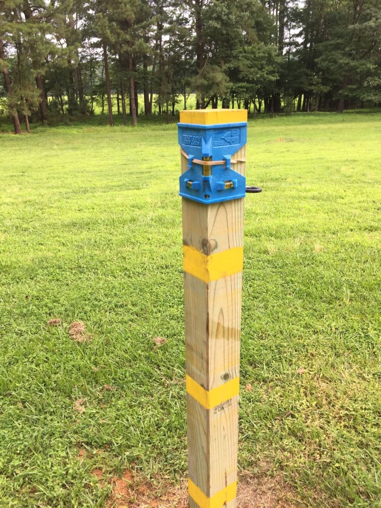
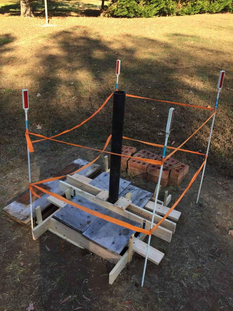
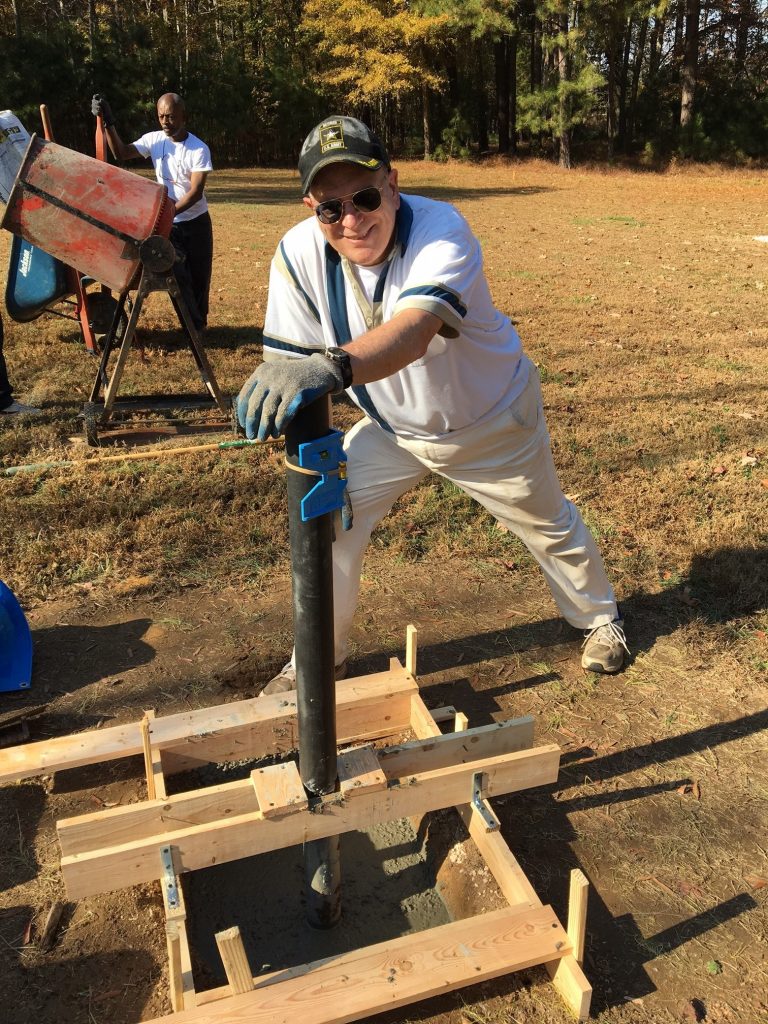
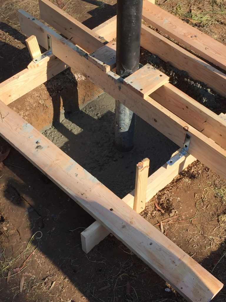
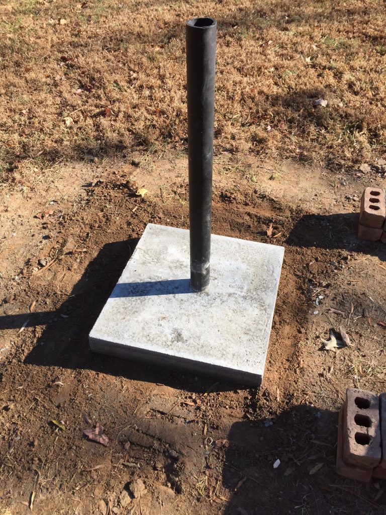
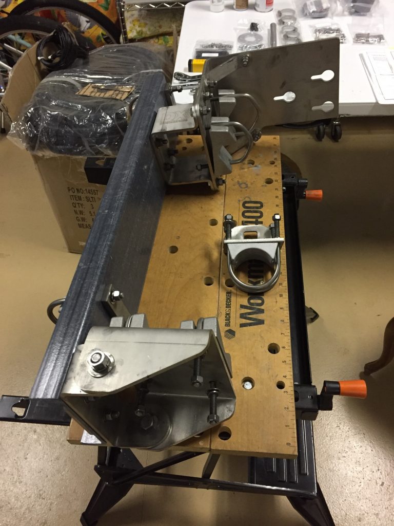
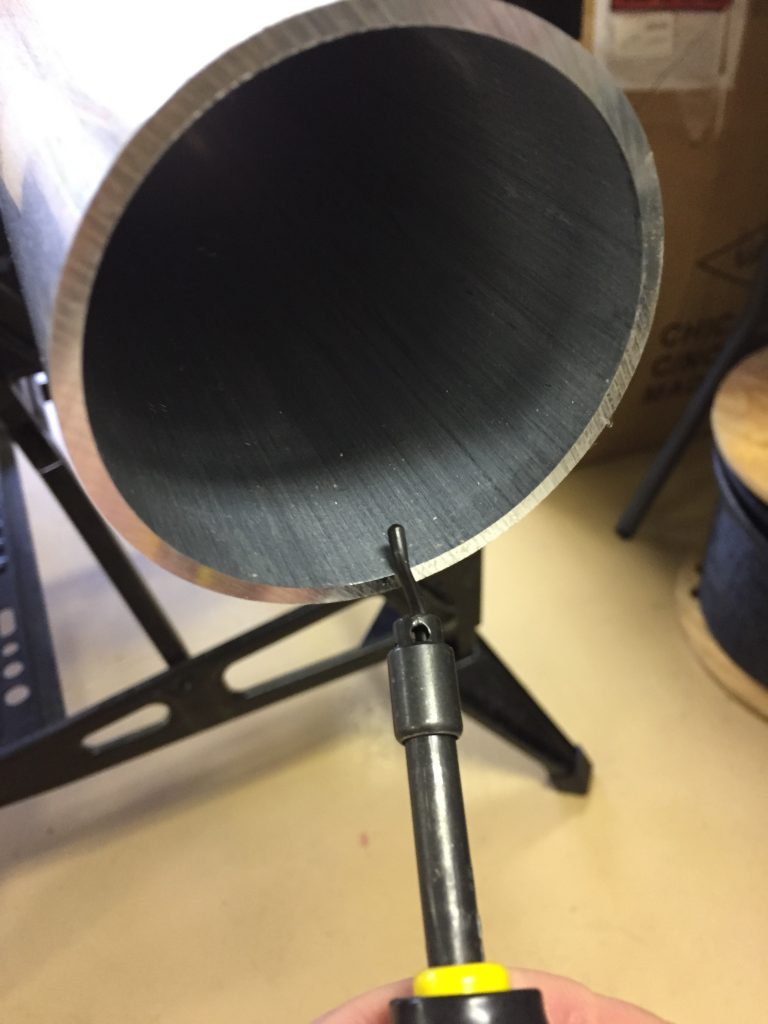
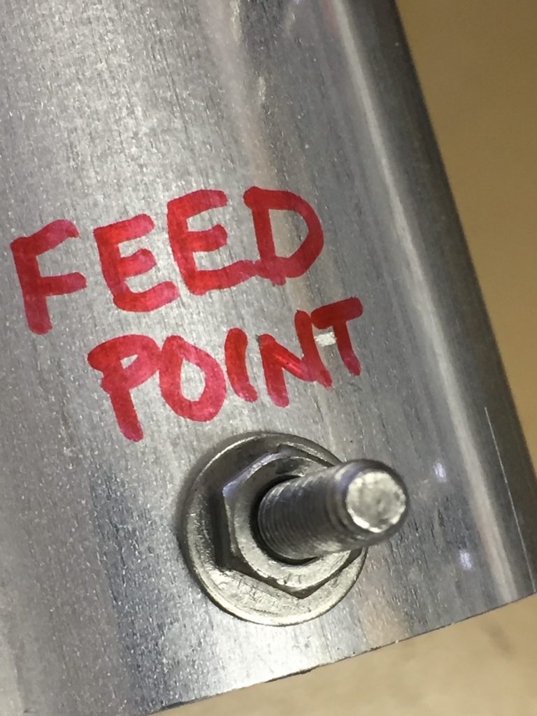
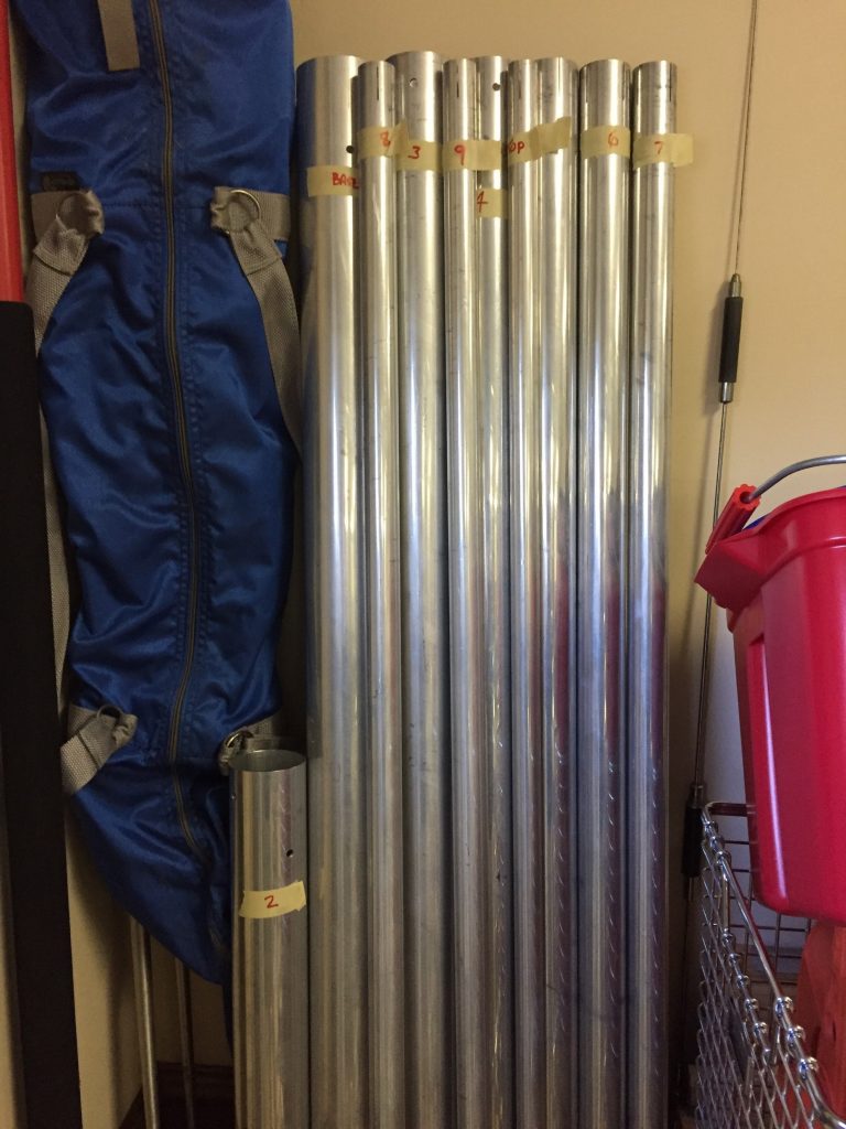
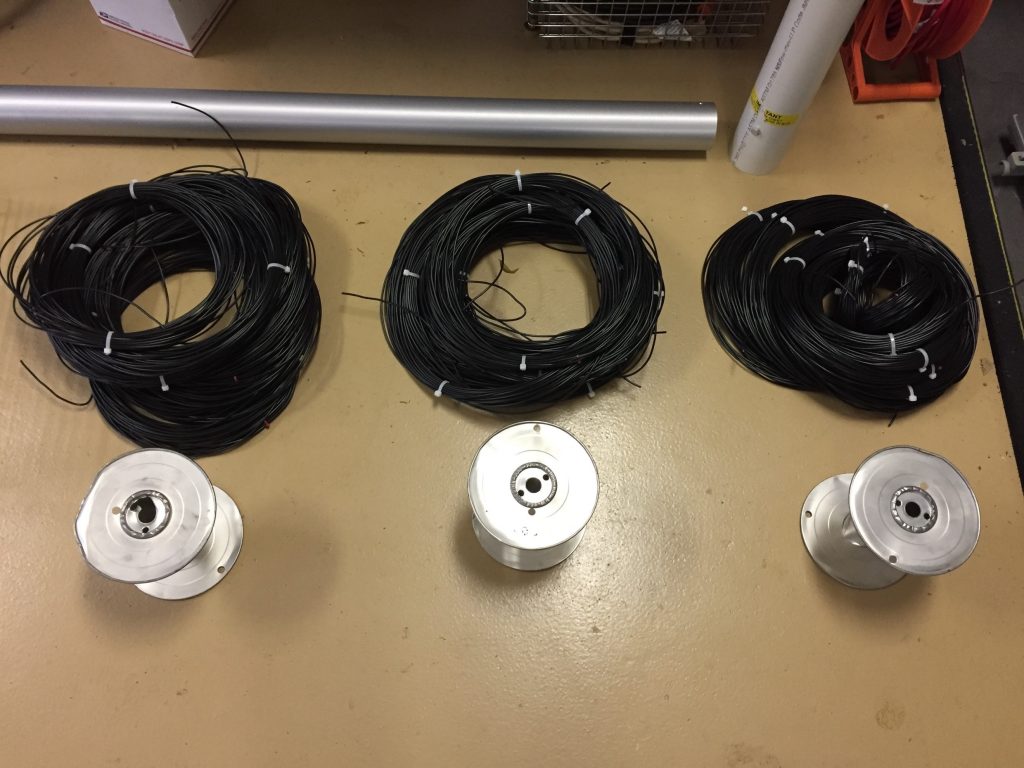
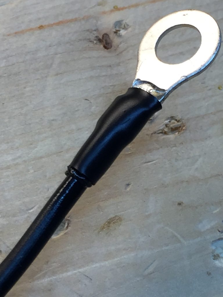
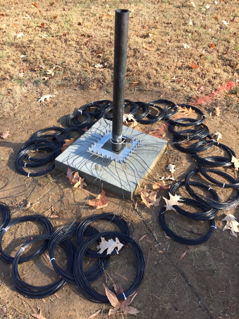
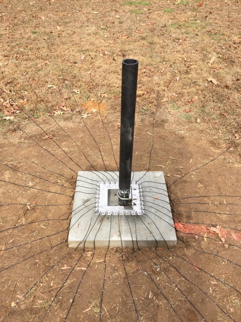
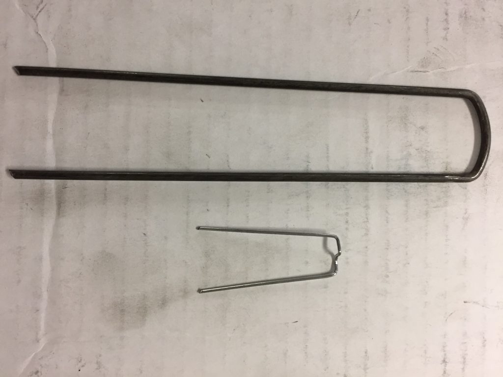
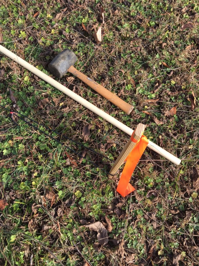
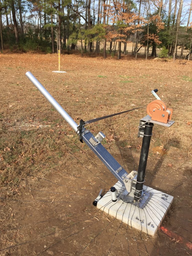
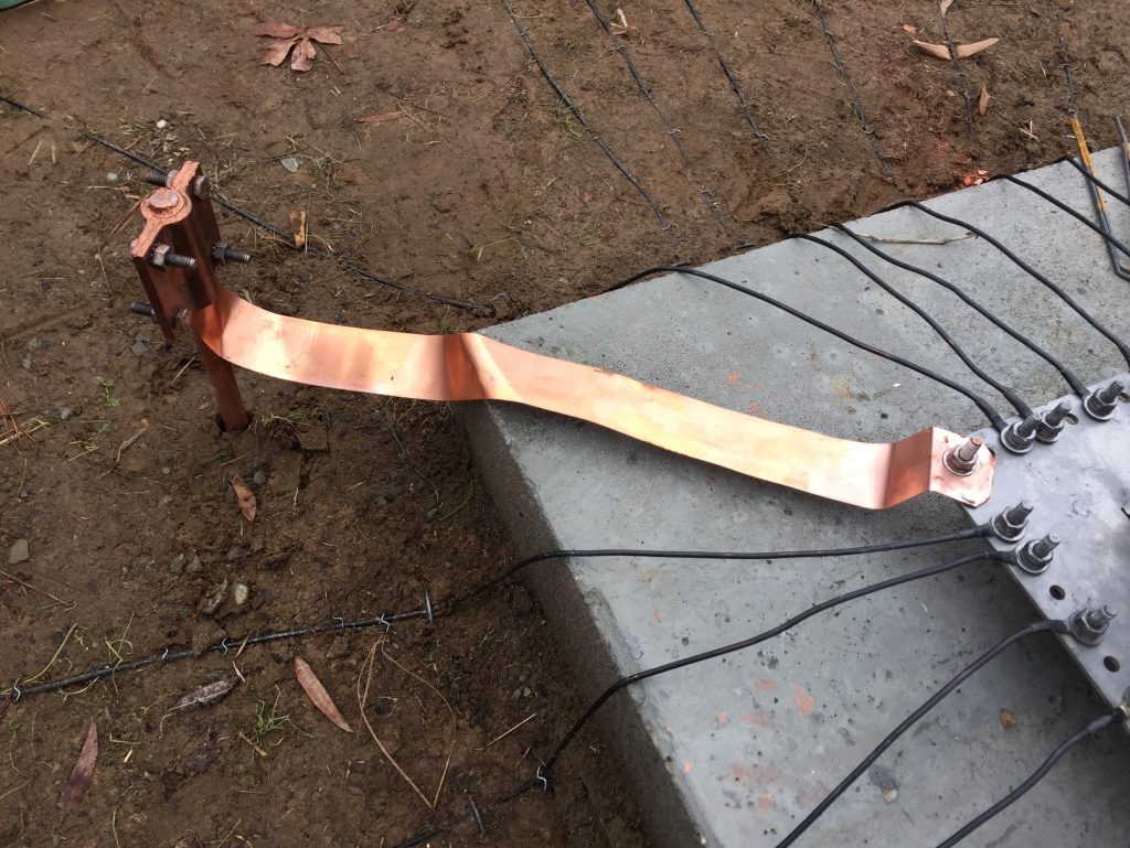
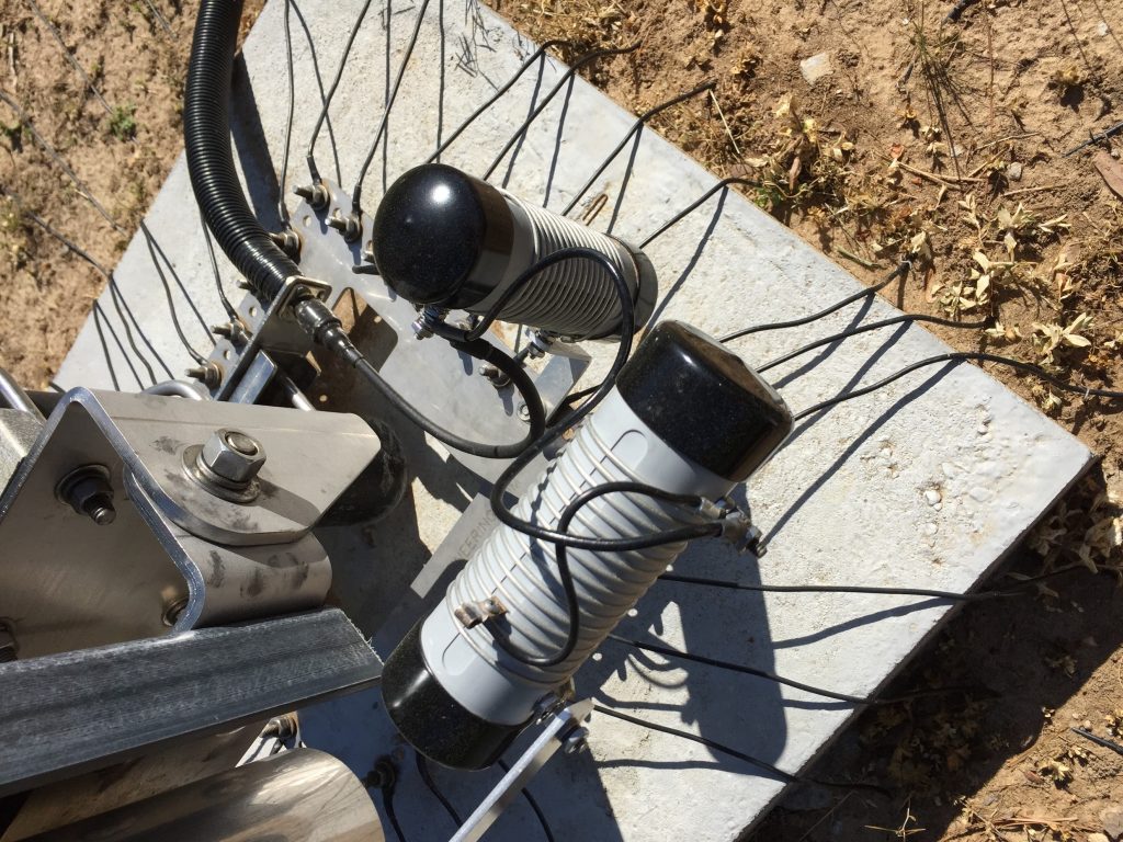
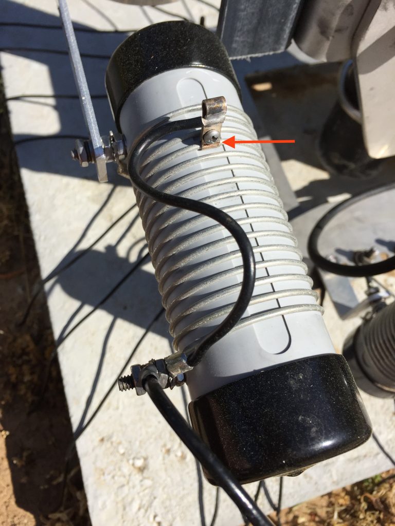
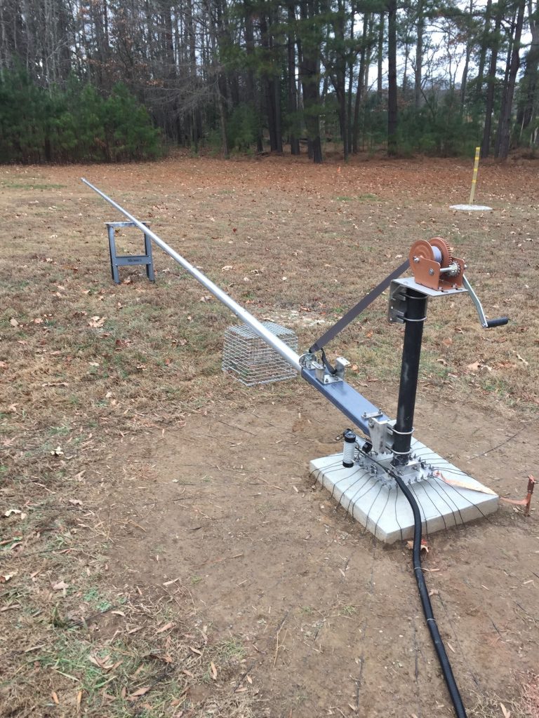
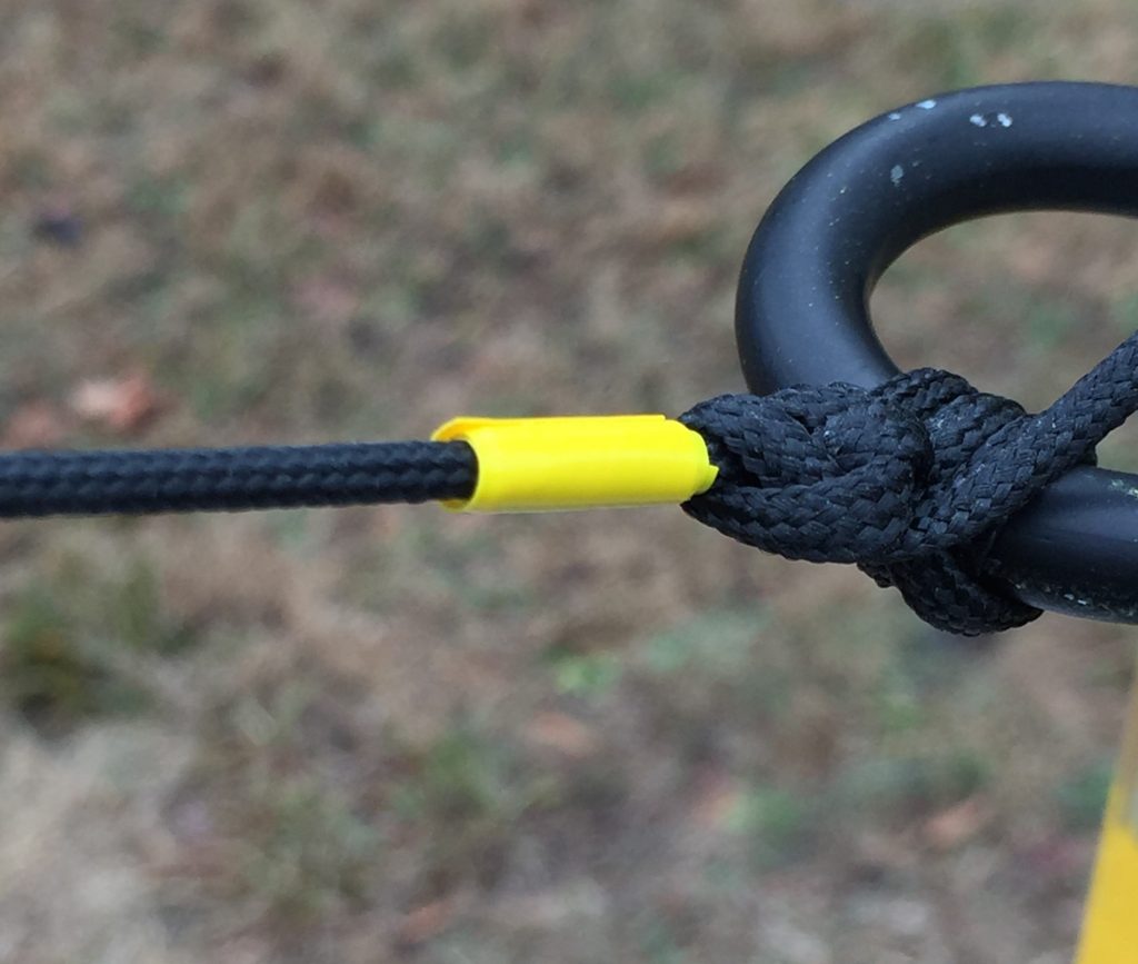
Having dug larger tower holes before I felt this one would be a bit simpler…so I let my XYL Toby, KLØSS, do the work! Just kidding, but she did help out a lot.The required hole measures 24″ x 24″ x 48″ deep and can be dug with a post-hole digger. A 4″-6″ gravel bed at the bottom allows for proper drainage. The support pole should be a minimum of 4′ below ground and 36″ above so you can attach the antenna’s lower mounting bracket.It took a couple days to dig the hole. In the interest of safety, we covered and marked it in the unlikely event some person (or animal) might stumble into it.The antenna’s capacity top hat requires four ground-mounted support ropes. These are not meant for structural integrity but rather to keep the top hat properly configured. Instead of ground mounting them, I installed four 4″ x 4″ x 8′ pressure-treated wooden posts buried 3′ deep, leaving about 5′ above ground where the ropes could be attached to an eyebolt. Having the support ropes anchored above ground allows for mowing around each post without difficulty. A two-axis post-leveling device made quick work of ensuring the posts were level in both directions.The toughest part of this installation was finding a suitable 3″ O.D. Schedule 80 metal pipe to mount the antenna to. It had to be purchased locally (that’s a story in and of itself). Fortunately, DX Engineering took my advice and is now selling a suitable mounting pipe to make this much easier. As with any tower base, the pipe required a wooden form to contain the concrete and hold the pole in place and plumb while the concrete set.The spot in the meadow next to our home would have been tough to access with a cement truck, so I decided to mix and pour the concrete myself. An internet application calculated that I would need twenty 80 lb. bags of 3000 PSI concrete, which I had delivered by a local supplier. I borrowed a small electric mixing machine from a fellow Ham and hired a couple of workers from my neighbor’s cabinet company to lend a hand. The mixing and pour went smoothly, and we completed the task in short order. We then let the concrete cure for about four weeks before installing the antenna Putting the antenna together began by carefully inventorying all of the parts. DX Engineering’s assembly instructions were easy to follow and the build went smoothly.I put the base assembly together first (below), using several different compounds to help protect the hardware and prevent the nuts/bolts from galling over time. Historically, I’ve used Penetrox to ensure that telescoping aluminum antenna elements would not seize together, and some form of Never-Seez to protect stainless steel hardware. But I learned recently from Tim, K3LR, that Jet-Lube SS-30 Copper Lubricant is very useful for covering all mechanical connection points. I had used it previously only for antenna ground rod to clamp assemblies. Note: Don’t use SS-30 on coax connectors as the ingrained copper in the paste can foul the threads, but for everything else, Tim says SS-30 is the way to go.DX Engineering offers an Adjustable Deburring Tool that really helps take any edges off the inner and outer circumferences of the aluminum antenna segments. The tubing is well-manufactured, but the tool proved useful in taking any slight edges off that may have remained.The antenna feed point is at the bottom of the mast, and it was helpful to mark all the vertical pieces to make assembly easier when the time came.Any low-band vertical antenna requires a good ground radial system, especially on 160m. The assembly manual recommends that a minimum of 32 radials, each 65′ long, be used with this antenna. Because we have a large meadow, I was able to form a circle around the antenna with a diameter of 200′ and installed thirty 100′ radials arrayed around the base of the antenna. The DX Engineering bulk radial kits come in 1,000′ lengths, and the insulated, UV-resistant wire should last much longer than bare wire.To help prolong the life of the radials, I used marine-grade shrink tubing on both the ring terminals and the free ends of the wire to minimize moisture wicking into them. DX Engineering’s stainless steel radial plate makes it very easy to connect up to 60 individual radials and serves as the attachment to the vertical support pole. Two different size C-clamp devices are available so make sure you get the correct one for the diameter of your pipe; I used the 3″ O.D. version. Keeping each individual radial wire coiled and secured with zip ties made the process of installing them around the perimeter very easy. I temporarily installed stakes at the intended free ends of each radial around the 100′ radius circle to make it easier to lay them out like the spokes of a wheel.The radials were laid in place and stapled to the ground; ultimately, they will bury themselves under any foliage you may have. Cutting a lawn very short in the late fall and laying out wire radials almost guarantees they’ll have disappeared within a few months. In the past, I used smaller lawn staples but found they really didn’t hold the wires down sufficiently. DX Engineering has much larger staples available (see comparison below), and I used 600 of them to hold the radials down—they’re definitely not coming up again!I divided each 100′ radial length into 20 five-foot segments and used a 5′ piece of PVC pipe as a measuring tool along the wire to space the staples out. I began stapling each radial at the radial plate and worked outward using a rubber mallet to set the staples. Starting at the radial plate and working toward the outer arc ensures they remain straight and at least slightly taut, as you can pull the radials securely outward if need be once you reach the perimeter.Test fitting of the pivot base and lower antenna assembly was next. The optional winch assembly allows one person to easily raise and lower the antenna and is well worth the extra expense. With a monopole antenna (as opposed to a triangular tower), I decided that a single 8′ ground rod would be sufficient. I attached the rod to one corner of the radial plate using a short copper strap. A generous amount of Jet-Lube SS-30 Copper Lubricant was used to ensure a good long-term electrical connection between the radial plate and ground rod.The antenna uses series and shunt tuning coils to yield a proper match at the base of the antenna. Movable taps let you adjust the series coil for your desired resonant frequency, followed by the shunt coil for the lowest SWR at that point.My only real complaint about this arrangement is that the taps are difficult to attach to the coil stock. As a practical matter, I found soldering them in place as described in the instructions didn’t work. Having said that, the mechanical taps have been in place now for almost four years without any failure, even during near legal limit digital operating.The vertical elements were assembled with the capacity top hat and its supporting rope assemblies attached. Make sure you understand and follow the assembly instructions for rigging the capacity top hat as it can be a bit confusing. A 190′ run of LMR-400 coax connects the antenna to the radio in the shack. Trenching and burying the coax was considered, but I elected instead to simply lay the cable on the ground and protect it with a full-length cover of corrugated wire-loom tubing.Once the antenna assembly was complete, a small crew assisted with holding the four top hat support ropes while I used the winch to raise the vertical. After adjusting the ropes so that the antenna was plumb and the top hat properly oriented, I marked each point on the rope at the support poles with a piece of colored tape to make it easy for one person to raise the antenna properly after lowering it for any required maintenance or impending weather event.
Our last step was to adjust the taps on the series and shunt
coils. We used a temporary 50′ coax connection to avoid body interaction with
the antenna, as recommended in the instructions. Using my RigExpert
antenna analyzer made this process a snap.
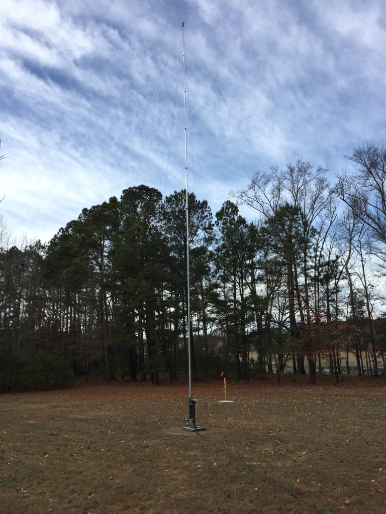
So, what does the final antenna look like and how does it
perform? With a combination of SSB, CW, and digital mode contacts, I was able
to work and confirm 100 countries for my Top Band DXCC award within one year. Three-plus
years later the total is up to 150 confirmed. Although I targeted the antenna’s
performance for the lower DX portion of the band, I can use my Ten-Tec external
tuner to achieve an acceptable match all the way up to 1.966 MHz. A project in
the works will use a remotely controlled coil-tap switch assembly at the
antenna base to provide a more efficient match throughout the entire band.
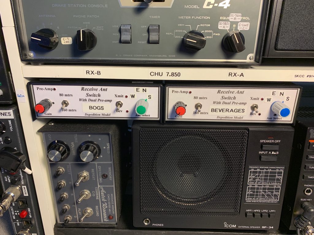
Vertical antennas are known for their vulnerability to noise—the Thunderbolt is no different. I installed two perpendicular, reversible direction receive-only antennas using the KD9SV Beverage switch control and preamplifier system, another great product available from DX Engineering. Combining the Thunderbolt with the Beverage receive antennas makes a flexible receiving combination, but that’s a story for another day.
This has been one of the more satisfying projects in my Ham career.
If you have the space available and want a great performing antenna on the Top
Band, I highly recommend the DX Engineering Thunderbolt. Good luck and good DX
on 160m!
Author: Dino Papas
Dino Papas, KLØS, is a frequent contributor to QST and the ARRL's new On the Air magazine and has been an amateur radio operator for over 50 years. You can contact Dino at kl0s@arrl.net.