
Over the years, due to long term exposure to noxious noise, I have developed occupational hearing damage. Consequently, for me it is very difficult to critically adjust amplitudes when it comes to listening to audio. Therefore, response adjustment of the DX Engineering NCC-2 was difficult for me to optimize settings for best performance. I needed an objective tool that provides a visible qualitative values to optimize the settings of the NCC-2. Switching to the Yaesu FTDX-101MP was a game changer for me, after having an Elecraft K3S. With dual S-meters and band scopes, integration of the NCC-2 phased output into the second receiver of my new transceiver made adjustments of the NCC-2 come alive for me. The performance of the NCC-2 was now objectively measurable resulting in increasing my ability to abolish signal fading (QSB) on HF. Details of my methods and connections are described here.
My approach for adjusting the NCC-2 can be accomplished with other transceivers that must be able to SYNC both receivers to exactly the same frequency and have independent S-meters and spectrum scopes. This includes the Yaesu FTDX-101D, Icom IC-7610, IC-7851, and the Kenwood TS-990S, and some FlexRadio models, of transceivers in current production. Discontinued transceiver models that have two separate receivers that can Sync with independent S-meters can work very well in this application, such as a FlexRadio5000A or C transceiver equipped with a second receiver.
My Yaesu FTDX-101MP is equipped with VC tune for both receivers, as well as the standard Contour, APF and other controls. As mentioned, the key feature is independent dual S-meters with simultaneous display for each receiver. Each receiver can display a bandwidth window for tuning with the option for independent band scopes and waterfalls for each. These features provide visually objective tuning indicators of the phased output of the NCC-2.
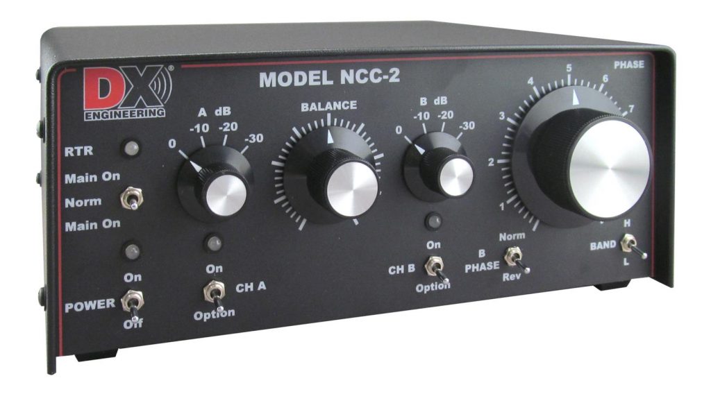
The DX Engineering NCC-2 Set Up
My NCC-2 is connected to a pair of the recommended Active Receive Vertical Antennas, presently sold as DXE-ARAV4-2P. I have the older models with the stainless whips spaced 40 feet apart. Having driven 8 foot ground rods for their mounting bases and amps hiding behind bushes, these antennas and whips are hardly noticeable in the front yard. Next, their RG6U cable is fed into the shack via DC pass grounding blocks and then to the NCC-2 port RX ANT CH A and B. As shown on page 21 of the NCC-2 Manual, the internal jumper configuration for BIAS TEE ENABLE was changed from factory default “Open” to “Jumpered-Shorted” to place DC power onto the coax to power the Active Receive Vertical Antennas. To protect them from transmitted RF, the Actives are automatically turned off during transmit with the transceiver’s amplifier PTT keying liner properly connected. Mentioned in the next section, details of the required keying cable appears in the NCC-2 manual pages 18 and 19.
The Yaesu FTDX-101MP Set Up
Since I am phasing two receive only verticals with the NCC-2, the transmit antenna is not connected. Only the actives’ phased signal output from the bottom SO-239 labeled “RADIO” on the NCC-2 is connected with a coax cable to the “ANT 3/RX” port on the back of the FTDX-101MP. Standard patch cables with male RCA-phono connectors provide the required keying lines, from my FTDX-101MP “TXD GND” connector to the “RADIO PTT” input on the NCC-2 and another cable from its key line pass-through “ACCY PTT” output to my amplifier “KEY IN or RELAY.”
Once powered on, pressing the FTDX-101MP FUNC button and the menu “Operation Settings” screen button allows access to the General menu. Press “ANT3 Select” to change the “ANT 3/RX” port to only be used as a receive antenna—NO TRANSMITTING ALLOWED out antenna port 3. Go back to the Main screen by pressing FUNC twice. Once this is done, use the touch screen on the transceiver Sub Receiver antenna selector box that says “ANT1” and select “RANT.” This selects the NCC-2 output on the “ANT 3/RX” port, now dedicated to RX only and never to transmit. To make sure no hot switching happens with the amp, the menu option in the MP is changed to a 30ms transmit delay. This allows the NCC-2 to turn off the power to the outboard receive antenna amps, preventing the transmitted amplified RF from damaging the receive antenna preamps. This delay allows full amplifier relay closure before RF hits them preventing hot switching.
Now, use the “Display” button choose the desired set up which shows two S-meters and bandpass windows, one for each receiver. Additionally, two separate band scopes and waterfalls may be displayed, by your choice. Also in the menu “Operation Setting” and “General,” one has the choice to select “Headphone Mix” to “Separate, Combined 1 or Combined 2.” Those settings change the amount of stereo mode for Main vs Sub receiver in the left and right ears when using headphones. However, I prefer to listen to a single speaker that is plugged into the FTDX-101MP “EXT SPKR A” port which provides the option of blended Main and Sub receiver audio, using Main and Sub AF Gain to balance each level. The audio channels blend without the signal bouncing effect in stereo headphones and I find that I use the speaker now more often than the headphones. I don’t experience fading as I did before and I don’t have the sound jumping from ear to ear to somewhere in the back of my head with headphones. For those who want to hear separate receiver feeds, plug in two separate speakers to get the option of only Main receiver audio from “EXT SPKR B” jack and only Sub receiver audio from “EXT SPKR A” jack. See page 16 of the FTDX-101MP manual.
What does this set up give you?
Turning on the NCC-2 with this setup enables the second receiver in the FTDX-101MP to be used as a maximum or minimum gain objective tuning indicator. Adjustment of the NCC-2 Balance and Phase controls allow me to obtain the best desired non fading signal. Truthfully, it is hard for me to tell qualitatively the audio difference in a CW signal that is s-2 vs s-8. But using the meter makes this evident. Without needing to use hearing to tune the NCC-2, the signal to the Sub Receiver is maximized. Watching the meters and scopes graphically shows how the amplitudes of the fading of signals changes between the transmit antenna on the Main receiver and the phased receive antennas on the Sub receiver. This is quite an eye-opener! All the while you can hear this change with stereo headphone or choose NOT to hear any fading of the combined audio signals with one speaker connected to “EXT SPKR A.” Additionally, you have a full set of RX controls for noise and interference reduction, especially VC Tune, and DNR, APF, Contour, Notch, Width and Shift and so on, for both receivers of the FTDX-101MP. You will be amazed at how many times an S-0 signal is perfect copy, as if it were S-9, to let you put ATNOs (All Time New Ones) into the log!
The usefulness of the DX Engineering NCC-2 has been shown in this article in concert with the FTDX101D/MP and similar high-end radios. Additionally, the NCC-2 can be of great value when considering radios without a receive antenna port, such as an Icom IC-7300 and the new Yaesu FTDX10. The NCC-2 provides these radios a separate receive antenna port with the option of protection for the front end by installing the DX Engineering Receiver Guard Plug-In Module, DXE-RG5000HD-PM. This is especially important if the INRAD RX7300 modification* was performed to the IC-7300. In a high RF environment, the NCC-2 with the Receiver Guard will provide a safe path for a receive antenna input while protecting the IF of the IC-7300 from burn out. Plus, this adds all the aforementioned benefits of the NCC-2 when working the weak ones or nulling noise in a loud city environment.
*The INRAD RX7300 Receive Input Modification was discontinued by the manufacturer in February 2021.
(Editor’s Notes: A very important aspect of using one of advanced transceivers with the NCC-2 is the fact that the levels of the separate antenna signals in the two receivers can be completely balanced with AF and RF controls. Use of the appropriate settings on the NCC-2 including Balance and Phase, the selection of separate receiver specific Attenuators and IPO/Preamps, along with careful adjustment of separate receiver AF Gain and RF Gain controls will make all the difference to your operational success. By the way, RF Gain should almost never be set to full clockwise for the best signal-to-noise results! So, whether the NCC-2 is adjusted to Null out noise or interfering stations, or to Peak desired signals as described above, you can always make a series of AF and RF adjustments to maximize reception and hear the transmit and receive antenna signals in perfect balance. This is a great example of the power of diversity reception with separate antennas feeding synced separate receivers.
The NCC-2 also offers the other type of phasing, noise canceling or nulling, by combining the signal from transmit antenna with the signal from a receive-only “noise sense” antenna for interfering signal and noise canceling. For additional information on antenna selections and operations of the DX Engineering NCC-2 Receive Antenna Phasing Unit, see the NCC-2 manual linked here.)
This story was edited by Rod Ehrhart, K8RR, DX Enginering technical support.