
(Editor’s Note: The following article is from the archives of experimenter, inventor, friend of the Ham Radio community, and founder of Clifton Laboratories, Jack Smith, K8ZOA (SK).)
I recently acquired a Harris RF-590 receiver with a memory backup battery of unknown age, but still holding a charge. Rather than wait for the battery to fail, and risk damaging the printed circuit board, I decided to replace it with a new battery.
As shipped from Harris, a 3.6V NiCd rechargeable battery is installed on the main control board to back up channel memory, allowing the receiver to retain channel settings when the power is removed. When a NiCd battery leaks, a corrosive fluid flows that will destroy printed circuit board traces. My Updates entry for 12 July 2007 shows the results of a leaky NiCd battery in an HP-8116A function generator. In that case, damage to the PCB was minimal.
Rather than replace the battery with another NiCd, I decided to use a NiMH battery which should last longer and should be less prone to leakage. Mouser stocks a pin-identical NiMH battery, Part No. 672-55615703 which costs $10.18 (Varta part number: 55615703012 from Newark for $11.31).
Tools required:
- Philips screwdrivers, No. 1 and No. 2 size.
- Large flat blade screwdriver.
- Soldering iron, solder and solder wick. I also used a vacuum desoldering tool.
- Replacing the battery took me about 45 minutes.
Procedure
You will need a clear workbench area large enough to hold the receiver.
Removing the battery pack will clear the channel memories, so if their contents are important to you write the values down and re-enter the data when the replacement is completed.
Step 1 – Remove the power cord and any attached cables. Remove the front and bottom chassis covers with the flat blade screwdriver. Both covers are held in place with quarter-turn Dzus fasteners.
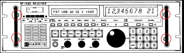
Step 2 – Loosen the four front panel retaining screws. Use a No. 2 Philips screwdriver. These are captive screws and should be loosened until they are free to move back and forth. The illustration below shows the screws partially obstructed by the rack handle. That was not the case on my receiver.
Removing the four retaining screws allows the front panel to hinge forward, 90 degrees, flat on the workbench.
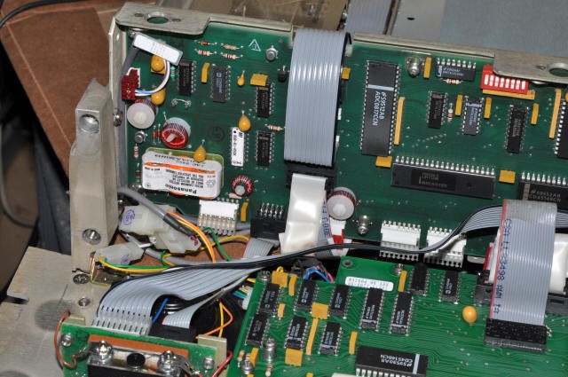
You should be able to see the controller board and backup battery. The battery is in the lower left corner of the controller board. (I do not know if this is the case for all revisions of the controller board.)
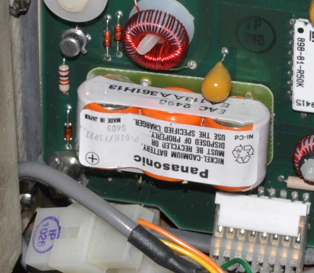
My receiver has a 1989 manufacture date, and the battery (Panasonic) has a date code I take to be 1994, some 16 years ago.
I assume this means the battery was replaced at least once. It also means that the replacement battery has lasted 16 years and still holds a charge, which is amazing.
That’s much longer than I’ve found in other equipment
Step 3:
Step 3 – The controller board is held in place with eight captive screws. Access to the bottom four screws is not possible with the front panel in place, so it is necessary to remove the two hinge screws securing the front panel to the main chassis.
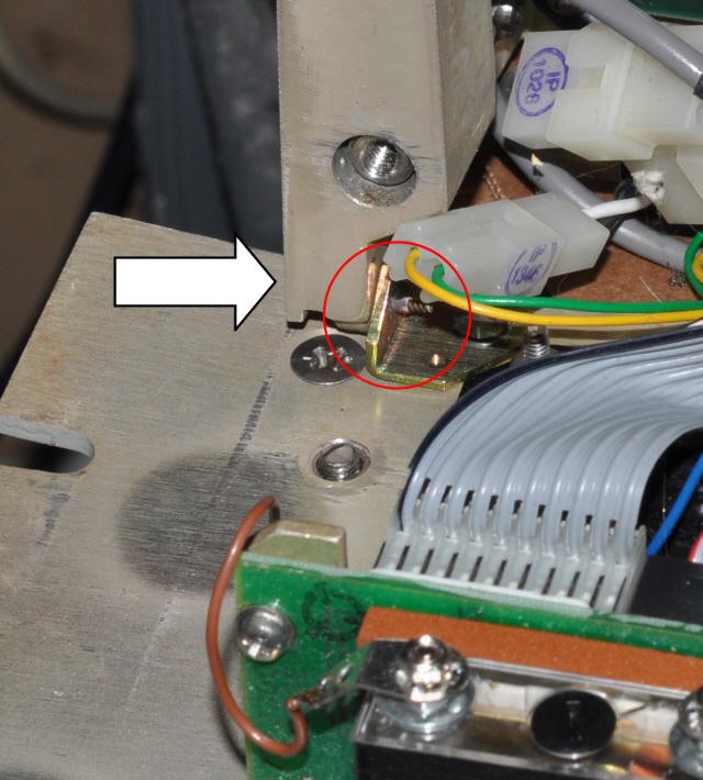
The photo below shows the left side hinge screw–the arrow points at screw head – reachable via a recess in the vertical bracket. The screw threads are visible just below the connector, and are centered in the red circle.
Remove the hinge screws from the left and right side. This detaches the front panel from the chassis. The cables are long enough to allow the front panel to move a couple of inches, which is all that is required.
You may find the next step easier to implement if you raise the receiver chassis a couple inches above the workbench or allow the front panel to overhang the bench’s front edge. If so, hold the front panel in place to avoid stressing the connecting cables.
Step 4 – Remove all the controller board plug-in cables. Most will have a “pull loop” attached to make the job easier. Note that cables attach from both the top and bottom of the board.
The cables are keyed to make it difficult to replace them improperly, but you may wish to make a note of which cable is associated with which jack.
Loosen the eight captive screws holding the controller board to the vertical panel assembly and carefully remove the controller board.
Step 5:
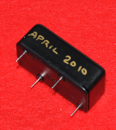
SRemove the old battery pack. The battery pack has four pins, two of which are internally unconnected but are used to mechanically hold the battery pack to the PCB, as well as plus and minus pins.
Use your favorite technique to unsoldering the battery. I started with solder wick, and then used a vacuum desoldering tool, while applying slight pressure to the battery pack with a small screwdriver between the PCB and battery pack bottom surface.
When the old battery pack is removed, clean the four mounting holes of any residual solder. Write the installation date on the new battery pack.
Step 6:
Install the new battery pack. The pin spacing is such that it can only be installed in the correct orientation.
Because I had difficulty removing the old battery pack, I decided to only solder the positive and negative pins, and leave the two unconnected pins unsoldered. This will make it easier to replace the battery next time, but reduces the mechanical soundness of the mounting, an acceptable exchange in my view.
After the battery pack is soldered in place, clip the four pins flush with the board.
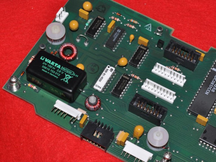
The photo shows the controller board with the new battery pack installed.
Step 7 – Reinstall the controller board and tighten the eight captive screws. When reinstalling the controller board, be careful not to trap connectors between the board and the shield the board mounts against. Also be careful not to stress the front panel cables.
Reattach all connectors to the controller board.
Reinstall the two hinge screws. Swing the front panel back to its normal position and tighten the four captive retaining screws. Replace the top and bottom covers. Reconnect the power cord and any attached cables.
This should complete your battery replacement. To charge the new battery, leave the receiver on for several hours.