
“End-fed” antennas, in particular the “End-Fed Half-Wave” (EFHW), are all the rage these days, particularly for portable operation. Throw a string over a tree branch, haul up one end, connect the other end to the matching transformer and—voila!—you’re on the air on multiple bands. And they do work pretty well. What’s the secret?
Voltage-Fed, End-Fed, or Both?
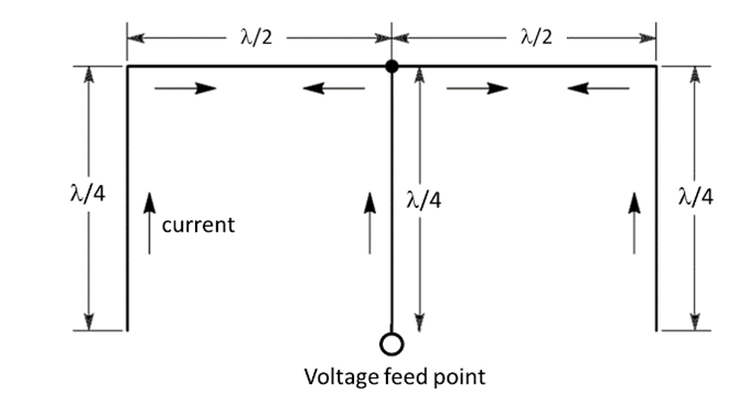
Let’s revisit an old term. What we call “end-fed” was long referred to as “voltage-fed,” meaning the feed point is located at a high-voltage/low-current point on the antenna. Remembering that impedance is the ratio of voltage to current, that point is also a high-impedance point. Since current is going to be pretty low at the end of the antenna—where would it go?—the end will be a high-impedance point, no matter what frequency.
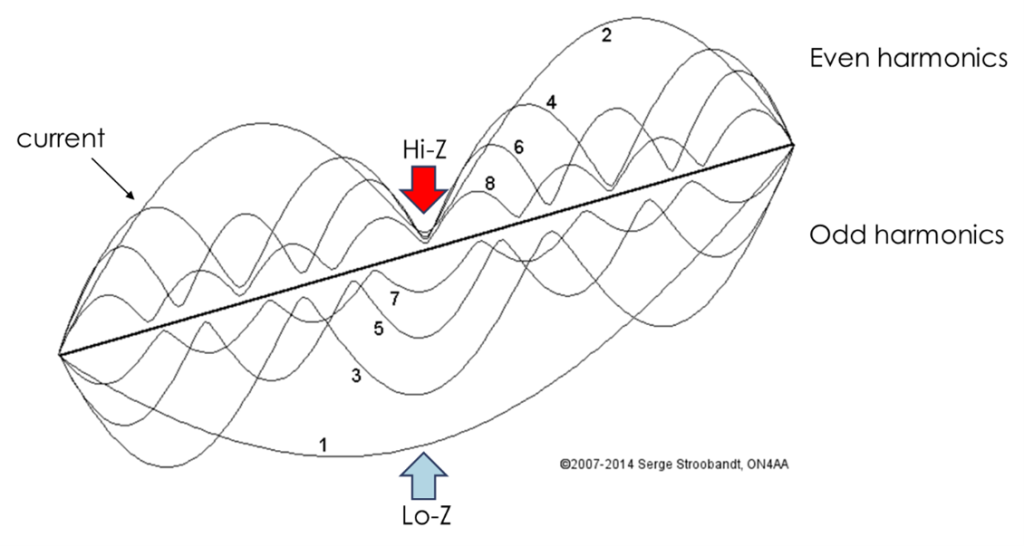
The feed point doesn’t have to be at the end to have a high impedance. For example, on its second harmonic, the familiar dipole becomes voltage-fed. Serge, ON4AA, made a very good, if complicated, drawing showing the current on a dipole for its fundamental and several harmonics. You can see that on the even harmonics, a center feed point is always high impedance, and on the odd harmonics, it is a low-impedance point. But…the one point where the impedance is always high is the end.
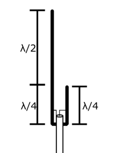
There are lots of voltage– or end-fed antennas. The classic Zepp (named after the Zeppelin airship on which it was used) is a half-wave dipole fed at one end. The popular J-pole is also an end-fed antenna—a Zepp with the half-wave radiating element sticking straight up instead of being horizontal. Here are two nice drawings from Owen, VK1OD, that show how a Zepp (top) and J-pole (bottom) are really the same antenna! (Would that make them a Zepp-pole-in?) The full article, “End Fed Zepp,” is online here.
Other examples of voltage-fed antennas include the Half-Square (top) and Bobtail Curtain (bottom):
Voltage Feeding
So how do you “voltage-feed” an end-fed antenna? You might just hook up the coax and use your antenna tuner. Unfortunately, the SWR from the high impedance load would result in a lot of loss in the coax! You need to transform the high feed point impedance down to something closer to 50 Ω. There are three common ways to do that:
Tuned Feeders
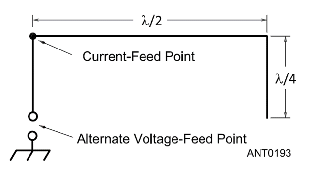
The Zepp and J-pole use the “tuned feeders” approach. A quarter-wavelength transmission line attached to a high impedance on one end will present a low impedance on the other. That’s how the Zepp was originally fed. The J-pole shorts one end of its “feeder” so that the other end will have a high impedance. Somewhere between the short and the antenna, there will be a point at which the impedance is close to 50 Ω, and that’s where you attach the feed line as shown above. You can apply this method to any voltage-fed antenna, but it will only work at one frequency. It’s not a multi-band solution.
Parallel LC Circuit
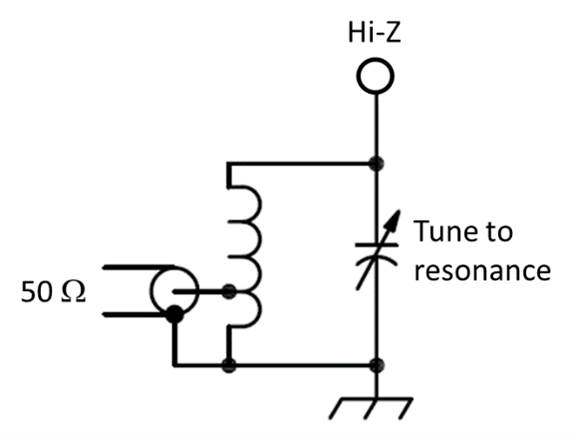
Another single-frequency or “resonant” approach is to use a parallel tuned circuit as shown below. The circuit is first tuned to resonance with the antenna attached. The parallel-resonant circuit presents a high impedance at the feed point. Then the coax to the transmitter is attached to the coil with a moveable tap and the tap position adjusted for the best match.
The tuned circuit acts a lot like the quarter-wavelength transmission line, doesn’t it? One end is at a low impedance (with respect to ground) and the other is at a high impedance. (There are many parallels between tuned LC circuits and transmission lines.) If you use this method at 100 Ω or more, be wary of the high voltages that are developed at the feed point! The variable capacitor must also withstand these voltages. Typical values for L and C are 15 µH and 75–150 pF for low-band operation. This is a narrowband matching network with typical 2:1 SWR bandwidths of less than 100 kHz.
Impedance Transformer
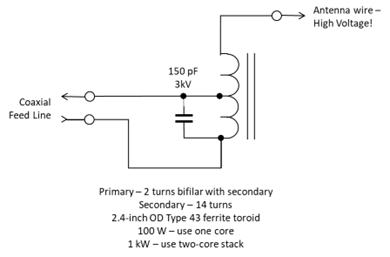
A solution that works over several bands is to use a broadband impedance matching transformer. This is the usual matching scheme for the popular EFHW antennas. The transformer’s impedance transformation ratio is the square of the turns ratio. As shown here, the turns ratio is 7:1 so the impedance ratio is 49:1 and type #43 ferrite will work over the entire HF range of 80–10 meters. The 150 pF capacitor compensates for winding inductance so the impedance ratio remains stable above 15 meters on the 24 and 28 MHz bands. The transformer design and many other EFHW details are explained in an excellent presentation by Steve, K1RF here.
Why 49:1?
When researching the EFHW and random-wire antennas, you will find transformers recommended with impedance ratios of 9:1 (turns ratio of 3:1) to 64:1 (turns ratio of 8:1). To pick the right turns ratio, you need to know the antenna feed point impedance. Most end-fed antennas will have a feed point impedance of 1000 to 5000 Ω. It’s actually pretty difficult to create impedances above 5000 Ω at RF because of stray capacitance and coupling to nearby conductive objects. The graph below looks at the transformer’s primary impedance with several different feed point impedances and turns ratios.
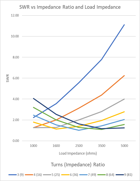
The “best” ratio would be the one that keeps the impedance at the coaxial cable connection close to 50 Ω over a wide range of feed point impedances.
Beginning with the 9:1 transformer, you can see that it would make a good match below 1000 Ω (SWR would be 1:1 at 450 Ω) but as the impedance rises, so does the SWR. (The same is true for ratios of 16 and 25:1.) If you use a 9:1 transformer at these high load impedances, beware—losses in the cable will partially mask the high SWR at the feed point.
Gradually increasing the turns ratio, you can see that a turns ratio of 6, 7, or 8 all produce reasonably low SWR across the expected range of feed point impedances.
The 49:1 transformer with a turns ratio of 7 (2 primary turns and 14 secondary turns) has an SWR below 3:1 for all of our feed point impedances, the lowest minimum SWR (1.02:1) and the lowest average SWR (1.69:1).
This is the transformer used in many commercial EFHW antennas, kits, and homemade antennas. If you do build this yourself, read and understand the presentation by K1RF first. A high-voltage ceramic capacitor should be used, even if you intend to operate at QRP levels. These capacitors are low-loss and relatively temperature stable.
The transformer can be used on most end– or voltage-fed antennas and would be a valuable addition to your antenna design gear. You should also have some non-inductive resistors (metal oxide or carbon composition) of various values to check the transformer at different load values. An antenna analyzer can measure the match across several bands.