The half-wave dipole is one of the most basic antennas in all of Ham radio. It also tends to get a bad rap; how many times have you heard somebody—possibly even yourself—say, “I’m only running 100 watts and a dipole.” Don’t sell your station short! A resonant half-wave dipole and 100 watts is a very effective station.
And one of the most common questions for one of the most ubiquitous antennas in the hobby is: “How high should I put my dipole?” The most common answer—as high as possible—is not necessarily the correct one. A lot depends on your operating style and who you want to talk to. Let’s take a look at these factors and see how high that dipole of yours should be.
Some Caveats
There are many variations of the dipole antenna. For purposes of this blog, we will focus on a half-wave center-fed dipole with 50-ohm coax as the feedline. Also, please note this blog is only a starting point of discussion and is not intended to be the defining article on antenna height. Volumes of work have been written on dipole antenna theory and design; I’ve provided some links at the end of this article if you want to study this in further detail.
Note that these factors may not apply to you. If you live in an apartment or on a small lot, your options for hanging that skyhook may be very limited. If that’s the case, put the dipole up in whatever configuration you can, preferably outside, and enjoy being on the air with what you can muster. However, do consider some of the topics presented here; you may find that your options for getting that dipole up may be more than first meets the eye.
Basic Dipole Characteristics
The half-wave dipole is two equal lengths of wire with the feedpoint in the center. Each wire, or element, is a quarter wavelength of the frequency you want to transmit on. The basic formula for dipole construction is dividing 468 by the desired resonant frequency, in MHz. As an example, a dipole cut for 14.225 MHz SSB is 468/14.225 = 32.9 feet total length. Divide 32.9 in half, and we see each element of this dipole needs to be 16.45 feet long.
Know Your Audience
If you have the real estate to install a dipole in multiple configurations, you have some decisions to make. Who, exactly, do you want to talk to? This may seem a silly question, but it’s one worth pondering. Are you interested in having a signal that is loud in your general region and not too worried about making DX contacts? Do you want to focus on working as much DX as possible? Are you interested in working anybody and everybody, no matter where they are from? These are real-world questions; a person interested in public safety and establishing a regional communications network during an emergency has different targets than a Ham trying to work DX halfway around the globe.
Generally speaking, a dipole is going to start exhibiting a
directional pattern once it is a quarter wavelength above terrain. Under these
circumstances, the antenna will radiate and receive broadside to the antenna
orientation. That is, if your antenna is oriented north to south, you will
notice better performance from the east and west. That’s not to say you won’t
hear or work anything off the ends of your dipole, but there will be some
attenuation from those directions.
The major lobes of radiation broadside to your antenna are going to have
different takeoff angles based on the height of your dipole above ground. Those
takeoff angles will determine at what angle your signal hits the ionosphere and
is reflected back to earth. Higher takeoff angles will help your signal be
louder closer to you. Lower takeoff angles will help your signal travel
farther, as they will bounce off the ionosphere much farther away, resulting in
a bigger “hop.”
Dipoles higher than a quarter wavelength can also be used to aim your signal in two specific directions. Say you live in the Midwest U.S. and want to maximize your capabilities to work European DX stations. By orienting your dipole northwest-southeast, your antenna is broadside northeast-southwest, which is bi-directional to Europe and out into the South Pacific. But this comes at the relative cost of not being as loud into South America and Asia.
Low Dipoles and Their Advantages
So what happens if your dipole is below a quarter wavelength high? Generally speaking, the radiation pattern will become omnidirectional, as much of your radiated signal goes out at much higher angles. For some applications (like long-haul DXing), this is bad. For others, a low dipole may be exactly what you’re looking for. EmComm operators may need to establish a regional network, within roughly a 500-mile radius, for example. Using a principle called Near-Vertical Incidence Skywave (NVIS), on 40 meters and lower, a low dipole can make a VERY effective antenna, blanketing an area to excellent effect. This has other applications; Hams who participate in domestic contests such as ARRL Sweepstakes often have a low dipole on 40 and 80 meters to work close-in stations they may not otherwise work on larger, higher antennas.
Consider what you want your antenna to do for you, then install accordingly. If possible, try putting up more than one dipole to cover different applications. Most of all, take notes and see how your antennas are performing. You can always experiment with different heights and orientations. I wish you success in your antenna experiments!
Further Reading
As I mentioned earlier, this is only a brief introduction to dipole performance and orientation. Those who want to do more in-depth research on how dipoles function and how they radiate at different heights above ground should investigate these resources:
Hands-On Radio: Experiment 82—Antenna Height by Ward Silver, N0AX. November 2009 QST.
Basic Antennas by ARRL. This book covers many types of antennas, from the basic dipole to vehicle antennas, and an introduction to antenna modeling. Written by the ARRL “Doctor” Joel Hallas, W1ZR.
Antenna Modeling with EZNEC 6+. This YouTube video by David Casler, KE0OG, goes over the basics of using the EZNEC antenna modeling software. A great tool for plotting the performance of your dipole.
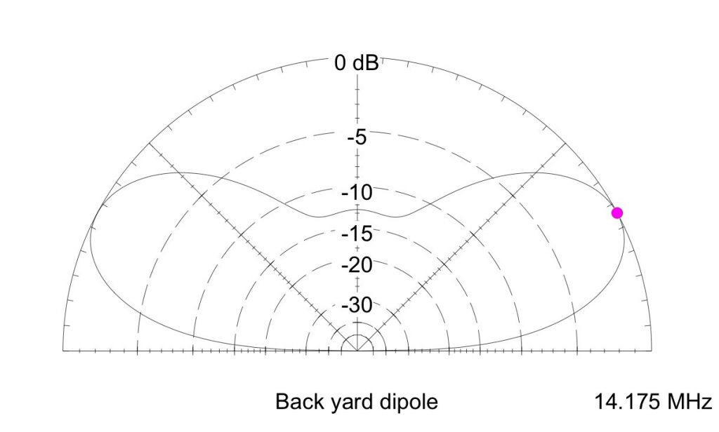
Take a look at these antenna plots that Ward Silver, N0AX, did with the EZNEC modeling program. The plot below shows the radiation lobes of a 20 meter dipole one-eighth wavelength above ground.
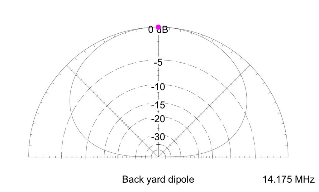
This plot below shows the lobes of the same dipole a quarter wavelength above ground.
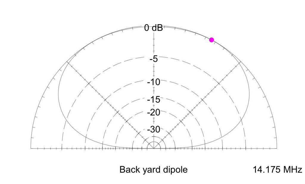
This final plot shows the lobes if the dipole is a half wavelength above ground. Antennas below a quarter wavelength above ground will have higher radiation angles and less directional capability. [Images reprinted with permission, November 2009 QST; copyright ARRL.]