
(Editor’s Note: The following article is from the archives of experimenter, inventor, friend of the Ham Radio community, and founder of Clifton Laboratories, Jack Smith, K8ZOA (SK).)
In working on a 10 watt high frequency 2SC1945 bipolar transistor amplifier, I built and evaluated three ferrite core transformers. These transformers are of the type used in input matching (50 ohms to lower impedance of the base circuit) and in the collector circuit (lower impedance to 50 ohm output).
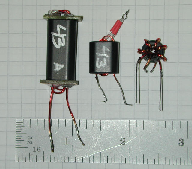
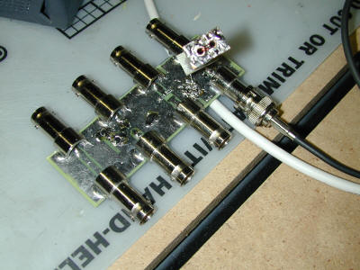
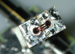
The three transformers are, from left to right:
1 turn : 3 turns, on a Fair-Rite 2843006802 core. The 1 turn wining is made from two lengths of 1/8″ rigid copper tubing with end plates from scrap pieces of printed circuit board material.
2 turns:5 turns, on a Fair-Rite 2843000202 core. (In ham radio nomenclature, the core is a BN-43-202.)
6 bifilar wound turns on a Fair-Rite 5943000201 core. (In ham radio nomenclature, the core is an FT37-43.)
If we consider a real transformer, i.e., one incorporating loss, leakage inductance and winding capacitance, the model shown below is frequently use to understand how the transformer behaves.
Lleakage is the leakage inductance
Rs is the series resistance of the winding
Cd is the distributed capacitance
Rc is the core loss
Lp is the magnetizing inductance
These parameters are “reflected back” to the primary, e.g.., we assume the series resistance is all in the primary, by treating it as the sum of the true primary resistance plus the secondary resistance scale by the transformer’s turns ratio. Of importance in our analysis are two elements of the model:
- Leakage inductance. Caused by magnetic flux that does not link both the primary and secondary
- Distributed capacitance. The turn-to-turn capacitance
At frequencies where the distributed capacitance is negligible, the degree of transformer “goodness” is often stated as the “coupling coefficient.” The coupling coefficient ranges from 0 to 1.00 and is a measure of the degree to which magnetic flux in the primary links with magnetic flux in the secondary.
If the coefficient of coupling is 1.00, the transformer is perfect and there is no leakage inductance. If the coefficient of coupling is 0, the two windings are completely isolated and there is no transformer action. Most useful audio an power transformers have a coefficient of coupling in the 0.97-0.99 range, although there are specific cases where a transformer may be intentionally designed with a low coefficient of coupling. It’s more difficult to obtain high coupling coefficients in radio frequency transformers, but a ferrite core based design offers the prospect of high coupling coefficient devices.
One definition of coefficient of coupling, k, is:

Where Lp and Ls are the primary and secondary winding inductances and M is the “mutual inductance.”
It’s often easier to determine the coefficient of coupling by measuring the primary inductance with the secondary winding open circuited and then again with the secondary winding short circuited, where:

L’p is the primary inductance measured with the secondary short circuited Lp is the primary inductance measured with the secondary open circuited
This method requires the winding Q to be “not too low” as stated in F.E. Terman’s Electronics Measurements, 2nd Ed.
Considering our simple transformer model, the effect of a short circuit on the secondary is illustrated below. The short circuit effectively removes the distributed capacitance, the core loss and the primary inductance from the model, leaving only the series resistance and the leakage inductance.
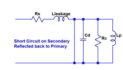
Likewise, if the transformer’s secondary is open circuited, and if (as is normally the case in a well designed transformer) the leakage and series resistance are small in comparison to the other transformer elements, the open circuit measurement effectively measures Cd, Rc an Lp.
Why are we so concerned with leakage inductance? The answer should be clear if we consider our model.
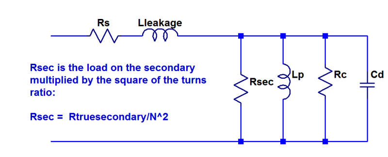
The transformer’s high frequency response is limited by the leakage reactance, again assuming (as is usually the case) that the transformer’s other imperfections are small compare with Lp’s reactance, Cd’s reactance and Rc, the core loss. If the leakage reactance is large compare with Rsec, the voltage developed across the secondary is reduced.
In this analysis, the secondary load resistance is multiplied by the turns ratio to place all the elements back to the primary reference. N is the ratio of secondary to primary turns and may be < 1, where the secondary has fewer turns than the primary.
In many cases, the transformer’s response can be modeled as just a function of the leakage inductance and the secondary resistance. As the frequency increases, the voltage developed across the secondary drops.
High frequency response may often be modeled as a simple RL circuit
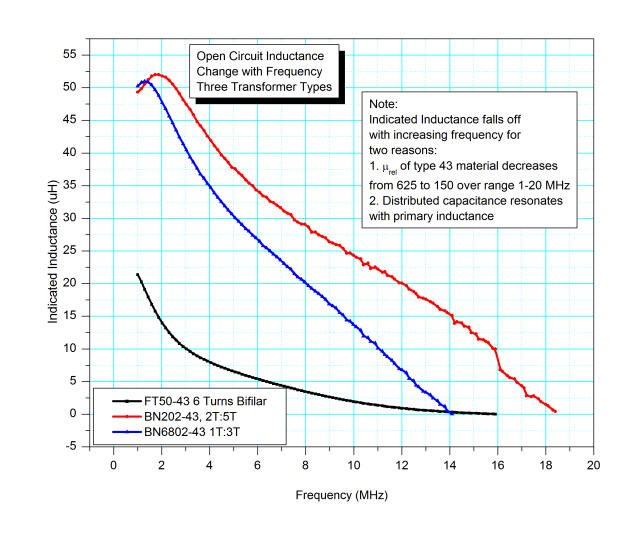
I measure the inductance of these three transformers over the range 1…30 MHz, using an HP8752B vector network analyzer and a home made reflection-mode test board. All transformers were connected with the largest number of turns to the VNA. For each transformer, I made two measurements, one with the secondary open and one with the secondary shorted.
This data shows the primary inductance. The drop in inductance with increasing frequency is cause by two factors. First, the relative permeability of Type 43 ferrite material is not constant over the frequency range 1…30 MHz. Second, the transformer’s distributed capacitance resonates with the primary inductance. The self-resonant frequency is where the measured inductance is zero. (In fact, data taken above this frequency shows the reactance shifts sign and becomes capacitive, as theory says.)
Fair-Rite provides the plot below showing the relative permeability (real and imaginary) for Type 43 material. The real permeability, u’s is the inductive determinative factor, i.e., as u’s drops, the inductance of a device using type 43 material proportionally decreases. u”s is the factor that drives core loss, or Q of an inductor made with Type 43 material.
Fair-Rite provides the following relationship between the complex permeability and inductance and loss.
From these equations, it should be obvious that the inductor Q, defined as ωLs/Rs is μ’s/μ”s. This explains why Type 43 material makes such low Q inductors. As the relative permeability plot shows, by 10 MHz, the maximum possible Q is 1, and this ignores other loss factors such as copper loss. And, even at 100 KHz, the maximum Q is around 8.
I’ve compute the coefficient of coupling for these three transformers, using the VNA data:
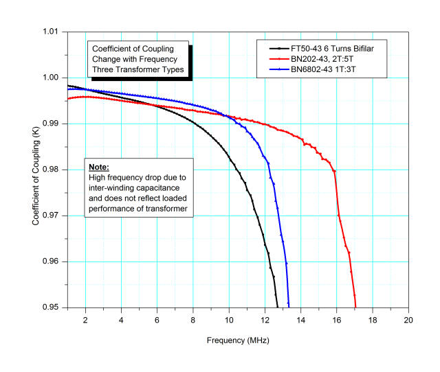
All three designs provide reasonably good coupling. The apparent falloff is not a real effect, however, and mostly results from the transformer’s winding capacitance reducing the apparent inductance. The leakage inductance remains relatively constant over the frequency range, so the ratio L’p/Lp artificially diminishes as Lp falls off.
The data shows that the transformer constructed with copper tubing has the best coupling coefficient when we look at data for frequencies low enough to ignore the distributed capacitance.
The real proof of how good these transformers are is seen by looking at how well the transform impedances. To demonstrate this, I added a 5 ohm load on the secondary of the 3:1 tubing transformer. These resistors have negligible parasitic inductance and capacitance at the frequency ranges in this sweep, so the result should be a pure 45 ohm resistance, plus whatever deviation is caused by transformer parasitic effects.
The VNA data below shows the result over the 1…30 MHz range.
The worst case is at 1.8 MHz, where the measured resistance is 43.5 ohms, but in general the measure resistance holds quite closely to the expected 45 ohm value.
The data also shows a series inductive element. Depending on the frequency, the inductive reactance corresponds to a series inductor of 400 to 130 nH. This is due to the leakage inductance as illustrated in the model.
More importantly, the measured response shows that the sharp drop in both coupling and primary inductance caused by the distributed capacitance does not have a serious effect upon the transformer’s actual performance. This is because the resistive load swamps the rather small effects of the transformer’s imperfections.
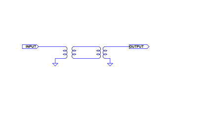
I also ran frequency response tests on two of the transformers over the range 1…100 MHz. These tests use two identical transformers, back-to-back with the side having the largest number of turns connected to the VNA’s ports. The arrangement is shown below. Assuming the transformers are more or less identical, we can assume the loss is equally divide between the two transformers. To obtain the performance of a single transformer, therefore, divide the backto-back data by two.
The data below is for the 1 turn : 3 turns, on a Fair-Rite 2843006802 core, transformer. At 28 MHz, it shows an insertion loss of 1.5 dB (dividing the 3.0 dB loss by two to reflect the performance of a single transformer.)
The data below is for the 2:5 turns on s, on a Fair-Rite 2843000202 core. It shows about 2.25 dB loss at 28 MHz for a single transformer, a bit less efficient than the tubing transformer on a larger core.
Since these two transformers do not have equal turns ratios, it may be a bit unfair to directly compare them. However, I believe the data shows that the transformer constructed with copper tubing is the best of the three designs.