
You’re hosting a party and someone arrives who probably wouldn’t have made your invite list. Maybe someone brought them along, your XYL said you had to invite them, or they asked themselves.
Do you try to ignore them? Tolerate them? Get them to leave?
Common-mode current (CMC) is much like that unwanted guest and just as annoying. It can cause SWR problems, erratic behavior of radio equipment, and even RF shocks when you touch metal parts of your rig. But you can get rid of CMC more easily than you think. Use a choke.
Common-Mode Causes
RF is a good thing. Without it, we wouldn’t have much of a hobby. However, sometimes we need to control its adverse effects.
Did you know acoax cable essentially hasthree conductors, not two? Due to the “skin effect,” current can flow along the inner surface of the coax shield as well as the outer surface—one on the center conductor, two on the shield.
In coaxial cables, differential mode current is the balanced current that flows on the center conductor and the inner surface of the shield in opposite directions. On the other hand, CMC flows on the outer surface of the shield and can cause radiation and interference. Differential mode currents are the good currents carrying the desired signal, while common-mode currents are the bad currents representing unwanted noise.
The problem is that an unbalanced current flowing between the antenna and the transmitter produces radiation. The coax effectively becomes an antenna that can cause interference to nearby electronic devices.
Chokes
It would be a bad move to choke unwanted guests, but you can choke unwanted RF problems.
A common-mode choke in RF applications acts like a filter, blocking unwanted radio frequency noise while allowing the desired signal to pass through. It does this by limiting the common-mode current that flows on the outer surface of the cable, which can cause interference and other issues. A choke will ensure that the coaxial cable’s shield doesn’t unintentionally become part of the antenna or receive unwanted signals, such as RF noise generated by the electronic devices in your house.
When the cable shield becomes part of the antenna, it alters the overall length of the antenna, changes its configuration, and alters the radiation pattern. As a result of this change in length, the antenna resonance also changes. Don’t confuse resonance with the frequency at which the minimum SWR occurs—resonance and minimum SWR are two different things. However, minimum SWR also changes when CMCs are flowing on the coax.
Hams often debate about how much common-mode impedance is necessary to attenuate the common-mode current. Some say 500 ohms is enough, but the actual value depends on the initial CMC and frequency. A Yagi on a tower may have much less current than an off-center-fed antenna near the ground. It’s best to have the highest practical impedance needed to choke the CMC, somewhere north of 1,000 ohms.
7 Signs You May Need a Choke
To choke or not to choke? Here are some simple tests and observations you can perform to help you decide.
- Running Your Hand Up and Down the Coax – With an antenna analyzer connected, running your hand along the coax cable can help you identify if the noise level changes, indicating common-mode currents.
- RF Burns – If you feel an RF burn when touching metal parts of your radio, it’s a strong indicator of common-mode currents.
- Erratic Radio Behavior – Your radio might exhibit strange behavior, including difficulty transmitting, high SWR readings, or complete shutdowns, especially during transmission.
- Garbled Audio – If your audio sounds distorted or garbled when transmitting SSB, it could be a sign that common-mode currents are affecting your audio processing.
- GFCI Outlets Tripping Common-mode currents can sometimes cause GFCI (Ground Fault Circuit Interrupter) outlets to trip.
- Disconnecting the Coax Shield – In receive mode, disconnect the shield of your coax cable, leaving the center conductor attached. If the noise level drops significantly, it suggests that the noise you’re hearing is likely to be common-mode noise.
- Unbalanced Antennas – Antennas that aren’t balanced, like end-fed wires, OCF dipoles, or those that are not symmetrical, are more prone to common-mode currents.
Buy or DIY
If you suspect common-mode currents are present, they can be minimized using the following:
- Common-mode chokes: These act as a high-impedance path for common-mode currents, effectively blocking them.
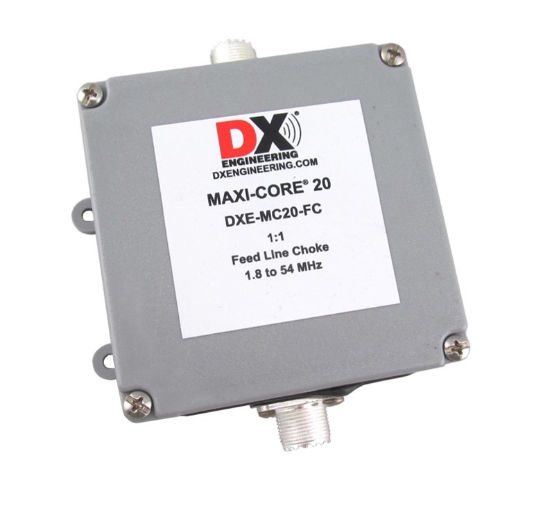
- Baluns: A 1:1 balun (balanced-to-unbalanced transformer) allows a balanced source or load to be connected to an unbalanced source or load, as well as blocks the transfer of common-mode currents onto your antenna or transmission line.
- A good earth ground: Adding a proper ground connection for the antenna and feedline can also help reduce common-mode currents.
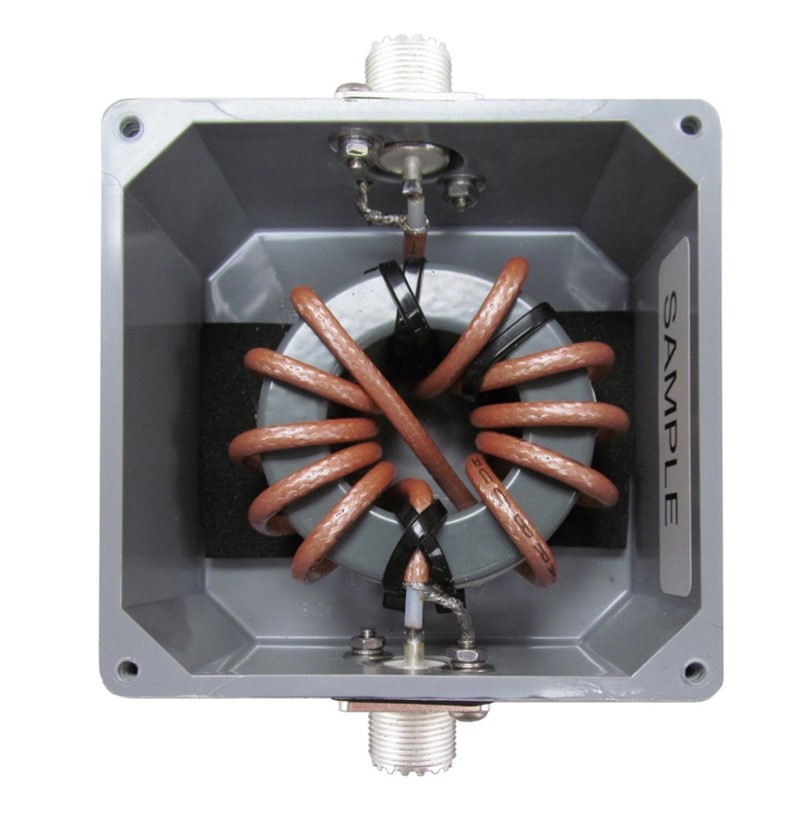
Commercially made chokes typically use wire or coaxial cable wound around or placed through ferrite toroids or beads. They’re often installed in PVC enclosures such as boxes or short PVC pipes with capped ends. The typical ferrite mixes used for the HF bands are types 31 and 43. Their resistances allow chokes to have much broader frequency ranges than air-wound coils.
Snap-on ferrites that fit over cable or wires are also available. They’re handy for adding additional choking capability or retrofitting chokes on currently installed coax cables.
Ham radio suppliers such as DX Engineering have a variety of each ready to install at your antenna or feedline. When using a coax cable, it’s advisable to have a choke at both ends of the cable for optimal results.
Want to roll your own? Chokes can be a reasonably simple build.
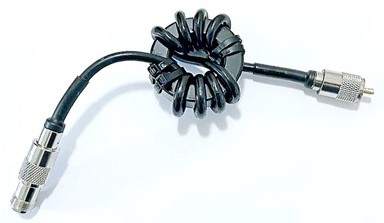
Some hams swear by air-core chokes. These are typically several scramble wound loops about four to six inches in diameter or wound around a piece of PVC pipe and secured with zip ties. It’s difficult to get repeatable results with scramble winding coax or guarantee a choke’s performance on a given frequency.
A better solution is to incorporate toroids into your chokes. You can wind the existing feedline around them or build a separate choke that can be easily added or removed. An FT240-43 or FT240-31 gives you enough room for several windings of RG-8X or LMR®-240UF. Squeeze in as many turns as practical. A multi-turn choke will have much better common-mode suppression than one with few turns.
Which toroid mix? Mix-31 has more common-mode attenuation on the 160-, 80-, and 40-meter bands. Chokes using Mix-43 have a better attenuation on the higher bands. An effective choke needs to have a high impedance for RF currents, typically exceeding 1,000 ohms.
Controlling Common Mode
Minimizing common-mode current requires increasing the impedance in the current’s path, effectively filtering out the undesirable CMC. In amateur radio antennas, we reduce common-mode current by placing a current choke or current balun in the CMC path. This tends to force equal currents in both halves of the antenna. If these currents are equal, there will be no unwanted current flowing in the coaxial shield. Chokes are generally placed at the antenna’s feedpoint, but you may find adding one where your feedline enters the shack may improve your results.