
“System” is a word that gets thrown around a lot. What does it mean from the perspective of an amateur radio operator? Generally, I think of a system as a collection of parts, each with a distinct function, connected together electrically or mechanically to achieve some purpose that none of the parts can accomplish by themselves.
What about “antenna system,” then? What does that include? I consider an antenna system to be the parts and pieces between your radio’s antenna connector and the air in which the electromagnetic waves travel to and from other stations. Not all of those parts and pieces carry current. Your coaxial cable’s plastic jacket is an important part of the antenna system as you’ll find out if it ever gets a hole! The same goes for that tree holding up one end of your dipole.
Parts of an Antenna System
Such a broad definition can make things look pretty complicated, but you can usually simplify a system by sorting the pieces into different categories. From a general point of view, your antenna system is made up of three types of parts: passive mechanical, active mechanical, and electrical. All of those parts contribute to how your station receives and transmits radio waves.
- Passive mechanical parts include things that hold your antenna up, keep it away from or in contact with other objects, support the feed lines, protect connectors and cables, and so forth. In most cases, these parts don’t have much of an electrical effect on how the antenna behaves.
- Active mechanical parts are things that by changing their characteristics also change the electrical behavior of the antenna system. This includes parts as simple as a switch or relay and as complex as a rotator or motor-driven tuning capacitor or coil. These generally have a big effect on antenna behavior and are probably intended to!
- If a part of the system carries RF signal current intentionally, it’s an electrical part. Feed lines, antenna elements, and tuning networks are all types of electrical parts. Parts that carry RF signal current unintentionally include items like the outside surface of coax shields, guy wires that pick up radiated signals, even the ground or a nearby metal roof. If enough current is carried, these are parts of your antenna system.
Let’s consider a simple antenna, say, a half-wave wire dipole for 20 meters fed by coaxial cable. What does that antenna system look like? If you start by designing and modeling this antenna in free-space, you’ll wind up with about 33 feet of wire (clearly an electrical part) having a classic figure-8 radiation pattern.
Since most of us don’t live in free-space (CQ NA1SS!) the antenna will be some fixed height above ground. The height makes a big difference in the elevation pattern, as the figure shows for several elevations. The electrical properties of the ground also determine how much of the signal reflects and how much is dissipated as heat. That makes the ground an important active mechanical part of the antenna system.
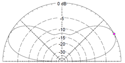
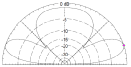
The figures above show the difference in elevation patterns for the very same dipole modeled over regular ground at a height of ½-wavelength on the left and ¾-wavelength on the right. Yes, the ground is an active mechanical part of this antenna system.
What is it that holds your antenna at the chosen height? Most dipoles are held up by non-conductive ropes attached to insulators at each end of the dipole. These are (hopefully) passive mechanical parts unless they break or get coated with conductive salt-water spray. But what are those ropes attached to? If they’re tied to or supported by a metal mast or tower you might find that the support begins to act as an antenna near frequencies at which it’s resonant. Guy wires that are resonant near the frequency of operation certainly will have an effect of a nearby antenna, picking up and re-radiating a signal. These mechanical components are passive on some frequencies and active on others.
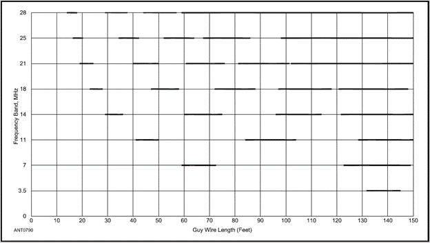
This figure from the ARRL Antenna Book shows the lengths of guy wires that are at or close to resonance in the eight amateur HF bands from 80 through 10 meters. In the bold ranges, the guy wires act as electrical parts, while elsewhere they are passive mechanical parts. A resonant guy wire close to a beam can result in significant pattern distortion or changes in SWR from the guy wire’s coupling affecting the feed point impedance.
Feed Lines
Then there is the feed line that gets (most of) your signal from the transceiver to and from the antenna. A perfect feed line would deliver all of the power from one end to the other while being completely transparent to the antenna and its radiated or received signals. Real feed lines have loss, though, and that loss increases with frequency. As SWR increases at the antenna, that results in additional feed line loss because the signal makes more than one trip through the feed line before it is all transferred to the antenna. This can make a BIG difference in your signal!
For example, three different antenna systems shown below change the feed line type and location of the impedance-matching antenna tuner. The antenna and its height above real ground are the same in each case. At 80 meters, the system loss in the tuner and feed line are 8.5 dB, and at 10 meters, the loss increases to 12.9 dB!
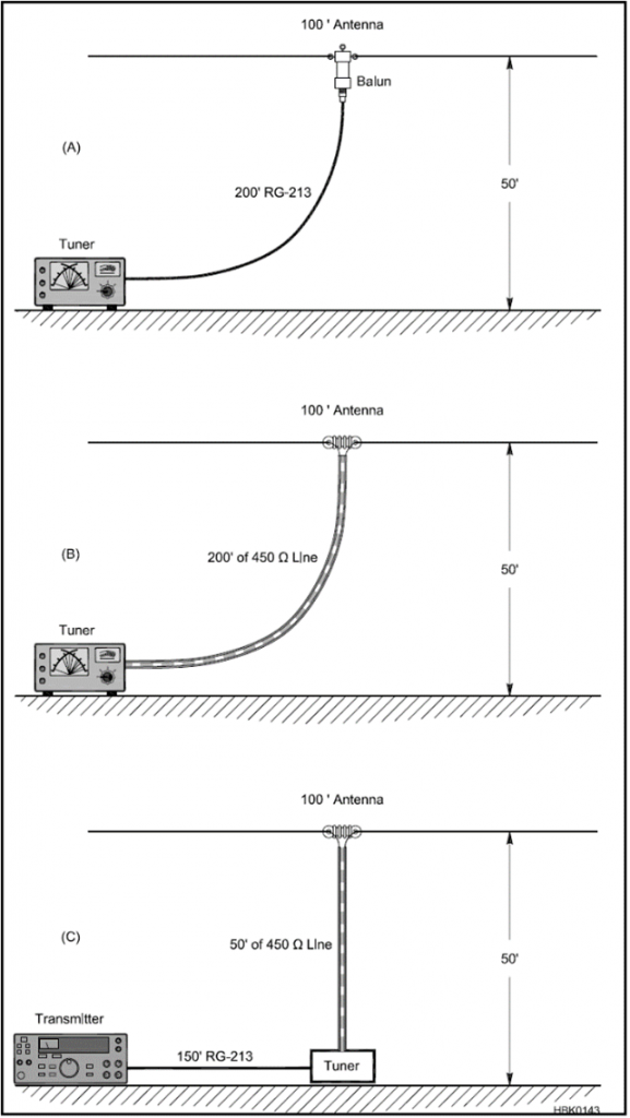
Changing the feed line to 450-ohm ladder line reduces the 80 meter loss to 1.8 dB and the 10 meter loss to 2.4 dB. If bringing ladder line all the way to the antenna tuner isn’t practical, you might use an auto-tuner directly under the antenna, connected to the transceiver with coax and the antenna with ladder line. This reduces loss even further to 1.2 dB on 80 and 0.9 dB on 10 meters.
This is a very good example of system-level analysis with real benefits for even this modest antenna system. You don’t have to have stacked Yagis or be operating UHF moonbounce to be rewarded by considering your system’s behavior. (There is a more complete discussion of this system in the Transmission Line System Techniques chapter of the ARRL Antenna Book where these figures are used.)
The feed line may also pick up a significant amount of common-mode current from the antenna, whether it is a dipole, a beam, or some other kind of antenna. For coax, the common-mode current flows on the outside of the shield, acting just like a “third wire” attached to the antenna’s feed point. (Open-wire feed line also has common-mode pickup with the current flowing equally on both wires.) The effect on feed point impedance and radiation pattern is unpredictable, and the common-mode path may conduct RF into your station where it can cause RFI. For these reasons, many antenna systems include a common-mode “choke balun” made from ferrite cores or by coiling the coaxial cable. Considering common-mode current paths is an important element of antenna system design.
Troubleshooting Antenna Systems
With experience, you’ll learn that troubleshooting an antenna really means troubleshooting the whole antenna system. If you think you have an antenna problem and you can’t see it lying on the ground or with half the driven element broken off, you’ll need to start at one end and work your way through to the other. For example, the author recently had an end-fed antenna that seemed to be misbehaving pretty badly, but after a few trips to the backyard raising and lowering the antenna, nothing looked obviously broken. As it turned out, one connector of a short coax jumper inside the station between a power meter and antenna switch wasn’t completely tight, and while it looked okay visually, it certainly wasn’t electrically! Getting the connector completely secure solved that problem, but the cause wasn’t what I initially expected.
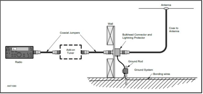
This is a typical antenna system for a simple HF station. Along with the add-on tuner, you might also have an antenna switch, power meter, band-pass filter, and other accessories. Notice that the ground system is also included in the antenna system. Where would you start testing if your antenna suddenly “went deaf” and had a high SWR? An end-to-end visual inspection is a good way to start, and sometimes the problem is something obvious.
Let’s say the inspection doesn’t identify the problem. Now is the time to put on your Antenna System hat and perform one test at a time to isolate the part with the problem. You can start at either end, but the most convenient method is to start at the station and replace the entire antenna system with a known-good dummy load attached as directly as possible to the output of the radio. Assuming the radio puts out full power without complaint, you then begin working your way toward the antenna. Replace each part in turn with a substitute or bypass it entirely with a known-good jumper connected to the dummy load. It helps to take notes of each test in your station notebook just to remind yourself of what you’ve tested and what you haven’t. Sooner or later, you’ll discover that moving the dummy load to the “other” side of Part X makes the problem reappear. Voila–you’re a system troubleshooter! Make sure to note the problem and its solution in the notebook, too.
There is a whole chapter on Antenna System Troubleshooting in the ARRL Antenna Book, with the introductory section written just for beginners. The chapters on Transmission Line Systems and the various basic types of antennas will help you understand all of the different elements of antenna systems, whether you have a dipole, a mobile whip, or beams. The more you know about antennas, the more tools you’ll have in your antenna systems toolbox. There’s a chapter on antenna measurements and instrumentation, too.
Some Darned Thing
Finally, I wouldn’t want to discuss troubleshooting without mentioning the inevitable “Some Da(r)ned Thing” or SDT. In my nearly forty years of electrical engineering, with a lot of troubleshooting experience of many different kinds of systems, I’ve learned to expect the unexpected. As Isaac Asimov observed, discoveries often result not from “Eureka!” but from “That looks funny…”
While you’re testing and inspecting, develop an ear for that little voice whispering observations. Maybe something smells a little hot or is a little discolored? What’s that wire hanging down on the output of the matching network? Where did the wing-nut go that was supposed to be holding down the gamma rod clamp? Is that a bird’s nest in the dish feed horn? The cosmic microwave background was discovered when Bell Labs personnel thought pigeon droppings were raising the noise floor of a big dish antenna! These things are never in the design documentation, but soon your “system sense” will keep you on the lookout for SDTs.